GenCade 2.0 Grid Point Attributes: Difference between revisions
mNo edit summary |
|||
| (4 intermediate revisions by the same user not shown) | |||
| Line 1: | Line 1: | ||
{{DISPLAYTITLE:GenCade 2.0 Grid Point Attributes Dialog}} | {{DISPLAYTITLE:GenCade 2.0 Grid Point Attributes Dialog}} | ||
There are a few things to take into consideration when defining the GenCade grid. The locations of the point of origin and ending point matter for the GenCade simulation to be successful. For GenCade, all references to "left" and "right", imagine the user is standing on land and looking out toward the water. The same goes for the grid orientation. The point of origin is the left-most location to be made available to GenCade. | There are a few things to take into consideration when defining the GenCade grid. The locations of the point of origin and ending point matter for the GenCade simulation to be successful. For GenCade, all references to "left" and "right", imagine the user is standing on land and looking out toward the water. The same goes for the grid orientation. The point of origin is the left-most location to be made available to GenCade. | ||
For example, for a GenCade grid in the northern Gulf of Mexico (Galveston, TX), the point of origin (Begin point) will be on the right hand side of the screen and the End point will be on the left. | For example, for a GenCade grid in the northern Gulf of Mexico (Galveston, TX), the point of origin (Begin point) will be on the right hand side of the screen and the End point will be on the left. | ||
As previously noted, there can only be one Begin point and only one End point as defined by this dialog. | As previously noted, there can only be '''one''' <u>Begin</u> point and only '''one''' <u>End</u> point as defined by this dialog. | ||
[[File:Grid_point_options.png|alt=GenCade Grid Point Attributes dialog showing the available options.|thumb|400x400px|Figure 1. ''GenCade Grid Point Attributes'' dialog showing the available options.]] | |||
=Creating a new point= | =Creating a new point= | ||
To create a new point, click the "Create Feature Point" tool and then click the appropriate location for that point in the main graphics window. You can create several new points before assigning a type to them. Each newly created point will default to be an "Unassigned" type. No points that remain "Unassigned" will be considered in the grid generation process. | To create a new point, click the "Create Feature Point" tool and then click the appropriate location for that point in the main graphics window. You can create several new points before assigning a type to them. Each newly created point will default to be an "Unassigned" type. No points that remain "Unassigned" will be considered in the grid generation process. | ||
=Defining the type for a point= | =Defining the type for a point= | ||
To define the type for the point, change to the "Select Feature Point" tool and double-click a point, or select multiple points you wish to assign the same type too and right-click then select "Assign Point Type...". A combo box (shown in Figure 1) on the resulting dialog will have several options to choose from: | [[File:Grid_refine.png|alt=GenCade Grid Point Attributes dialog showing the Refine option and resolution parameter.|thumb|400x400px|Figure 2. ''GenCade Grid Point Attributes'' dialog showing the Refine option and resolution parameter.]]To define the type for the point, change to the "Select Feature Point" tool and double-click a point, or select multiple points you wish to assign the same type too and right-click then select "Assign Point Type...". A combo box (shown in Figure 1) on the resulting dialog will have several options to choose from: | ||
*'''Unassigned''' | *'''Unassigned''' | ||
*'''Begin''' | *'''Begin''' | ||
| Line 22: | Line 20: | ||
To return to the Grid Coverage wiki page, click [[Gencade Grid Coverage|<u>here</u>]]. | |||
For information about other dialogs, select from the options under '''Categories''' below. | For information about other dialogs, select from the options under '''Categories''' below. | ||
[[Category:GenCade Dialogs|G]] | [[Category:GenCade 2.0 Dialogs|G]] | ||
[[Category:GenCade|G]] | [[Category:GenCade|G]] | ||
Revision as of 14:38, 28 March 2024
There are a few things to take into consideration when defining the GenCade grid. The locations of the point of origin and ending point matter for the GenCade simulation to be successful. For GenCade, all references to "left" and "right", imagine the user is standing on land and looking out toward the water. The same goes for the grid orientation. The point of origin is the left-most location to be made available to GenCade.
For example, for a GenCade grid in the northern Gulf of Mexico (Galveston, TX), the point of origin (Begin point) will be on the right hand side of the screen and the End point will be on the left.
As previously noted, there can only be one Begin point and only one End point as defined by this dialog.
Creating a new point
To create a new point, click the "Create Feature Point" tool and then click the appropriate location for that point in the main graphics window. You can create several new points before assigning a type to them. Each newly created point will default to be an "Unassigned" type. No points that remain "Unassigned" will be considered in the grid generation process.
Defining the type for a point
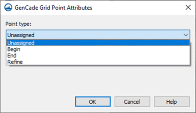
To define the type for the point, change to the "Select Feature Point" tool and double-click a point, or select multiple points you wish to assign the same type too and right-click then select "Assign Point Type...". A combo box (shown in Figure 1) on the resulting dialog will have several options to choose from:
- Unassigned
- Begin
- End
- Refine
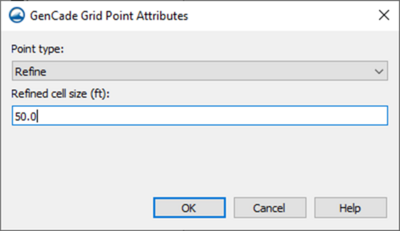
If Refine is chosen, then an entry box will appear for the user to enter the resolution to be considered for that point (or point's) location. The resulting dialog for the Refine option is shown in Figure 2.
To return to the Grid Coverage wiki page, click here.
For information about other dialogs, select from the options under Categories below.

