CMS-Flow/Culverts: Difference between revisions
| (4 intermediate revisions by the same user not shown) | |||
| Line 7: | Line 7: | ||
== Early SMS versions (< 13.4) == | == Early SMS versions (< 13.4) == | ||
Previous documentation (Link given below) described the formulation and implementation of Culverts in CMS, detailing input requirements for SMS versions up to 11.2. This implementation required hand-manipulation of the CMS-Flow parameter files to add in lists of cells and option values. | Previous documentation (Link given below) described the formulation and implementation of Culverts in CMS, detailing input requirements for SMS versions up to 11.2. This implementation required hand-manipulation of the CMS-Flow parameter files to add in lists of cells and option values. | ||
* [https://erdc-library.erdc.dren.mil/xmlui/handle/11681/1983 2013 - Culvert CHETN] | * Publication - [https://erdc-library.erdc.dren.mil/xmlui/handle/11681/1983 2013 - Culvert CHETN] | ||
* [[Media:Culvert SMS11.2setup.zip| 2013 - Original SMS 11.2 setup files]] | * Data - [[Media:Culvert SMS11.2setup.zip| 2013 - Original SMS 11.2 setup files]] | ||
== Future SMS versions (13.4.x) == | == Future SMS versions (13.4.x) == | ||
| Line 16: | Line 16: | ||
* <span style="color:red">Important:</span> Culvert feature arcs are direction specific and should begin on the '''Bayside''' of the culvert and end with the '''Seaside''' location. | * <span style="color:red">Important:</span> Culvert feature arcs are direction specific and should begin on the '''Bayside''' of the culvert and end with the '''Seaside''' location. | ||
* The "Structures" coverage will need to be applied to the CMS Simulation in order to export the appropriate cards to the parameter file. | * The "Structures" coverage will need to be applied to the CMS Simulation in order to export the appropriate cards to the parameter file. | ||
== CMS-Flow specific information == | == CMS-Flow specific information == | ||
| Line 91: | Line 57: | ||
| MANNINGS_COEFFICIENT ||YES ||1 ||<real> || || | | MANNINGS_COEFFICIENT ||YES ||1 ||<real> || || | ||
|- | |- | ||
| INVERT_ELEVATIONS ||YES ||2 ||<real> <real> || ||Bay, then Sea | | INVERT_ELEVATIONS ||YES ||2 ||<real> <real> || ||Bay, then Sea (Values negative down) | ||
|- | |- | ||
| ENTRY_HEAD_LOSS_BAY ||YES ||1 ||<real> || || | | ENTRY_HEAD_LOSS_BAY ||YES ||1 ||<real> || || | ||
| Line 124: | Line 90: | ||
CULVERT_STRUCT_END | CULVERT_STRUCT_END | ||
</pre> | </pre> | ||
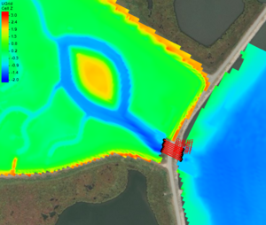
[[File:Culvert project.png|thumb|alt=Grid representing a Poplar Island wetland cell showing bathymetry and the location of the applied culvert structure.|Grid representing a Poplar Island wetland cell showing bathymetry and the location of the applied culvert structure.]] | |||
== Example Case == | |||
One example case for Culverts is described below and example files are provided in the next section. | |||
This example introduces a grid representing a wetland cell on Poplar Island in Chesapeake Bay. Several segments over the shoreline indicate the locations for the culvert structures. | |||
The grid and bathymetry is shown in the figure to the right with the culvert structures identified by feature arcs. | |||
== Input and output files == | == Input and output files == | ||
Latest revision as of 21:21, 26 November 2024
Introduction
Culverts are a common coastal engineering structure typically used in coastal wetlands to control waste and storm water discharges, act as salinity barriers, optimally distribute freshwater, and manage sediment transport (Figure 1). In coastal applications, the culverts often connect open water bodies of similar water surface elevation to enhance flushing or conduct flow through levees or causeways. Since culverts are a significant component of hydrodynamic and sediment transport controls in the coastal zone, it is important that the CMS simulates their effects. The implementation of culverts in the CMS is based on equations developed by Bodhaine (1982).
Usage of Culverts for CMS in the SMS
Early SMS versions (< 13.4)
Previous documentation (Link given below) described the formulation and implementation of Culverts in CMS, detailing input requirements for SMS versions up to 11.2. This implementation required hand-manipulation of the CMS-Flow parameter files to add in lists of cells and option values.
- Publication - 2013 - Culvert CHETN
- Data - 2013 - Original SMS 11.2 setup files
Future SMS versions (13.4.x)
A new "Structures" coverage has been added beneath the CMS-Flow model option in SMS 13.4 and later. This one coverage will handle Culverts as well as three other types: Rubble Mounds, Weirs, and Tide Gates.
- Culverts are added to this coverage with the placement of Feature Arcs.
- Important: Culvert feature arcs are direction specific and should begin on the Bayside of the culvert and end with the Seaside location.
- The "Structures" coverage will need to be applied to the CMS Simulation in order to export the appropriate cards to the parameter file.
CMS-Flow specific information
The parameters/selections for each Culvert feature arc will be exported to the ‘.cmcards’ file in the form of a block of values. This implementation has been confirmed to work with CMS 5.3.12 and later.
- The Culvert parameter cards needed for each culvert are added to a structure block with a corresponding BEGIN/END statement for each culvert are listed in the table below.
- Most cards take one parameter, others take two. This is defined in column 3.
- Cards that are dependent on other choices are indicated in column 5.
- In cases where multiple values are to be written for a card, the value corresponding to the Bayside should be written first followed by the Seaside value.
- For readability and to be consistent with other cards in the .cmcards file, all values should start in column 36 and 2 spaces written between each value per line if more than one.
| Cardname | Indent 2
spaces? |
Number
of vals |
Type of value
written |
Dependent on | Notes |
|---|---|---|---|---|---|
| CULVERT_STRUCT_BEGIN | NO | 0 | N/A | ||
| CELLS | YES | 2 | <int> <int> | Bay, then Sea | |
| TYPE | YES | 1 | ‘CIRCLE’ or ‘BOX’ | ||
| FLAP_GATE | YES | 1 | ‘ON’ or ‘OFF’ | ||
| RADIUS | YES | 1 | <real> | TYPE == ‘CIRCLE’ | |
| WIDTH | YES | 1 | <real> | TYPE == ‘BOX’ | |
| HEIGHT | YES | 1 | <real> | TYPE == ‘BOX’ | |
| LENGTH | YES | 1 | <real> | ||
| DARCY_FRICTION_FACTOR | YES | 1 | <real> | ||
| MANNINGS_COEFFICIENT | YES | 1 | <real> | ||
| INVERT_ELEVATIONS | YES | 2 | <real> <real> | Bay, then Sea (Values negative down) | |
| ENTRY_HEAD_LOSS_BAY | YES | 1 | <real> | ||
| ENTRY_HEAD_LOSS_SEA | YES | 1 | <real> | ||
| EXIT_HEAD_LOSS_BAY | YES | 1 | <real> | ||
| EXIT_HEAD_LOSS_SEA | YES | 1 | <real> | ||
| OUTFLOW_ANGLES | YES | 2 | <real> <real> | Bay, then Sea | |
| CULVERT_STRUCT_END | NO | 0 | N/A |
An example culvert block is shown below:
CULVERT_STRUCT_BEGIN
  CELLS                             14334  14348
  TYPE                              BOX
  FLAP_GATE                         OFF
  HEIGHT                            0.9
  WIDTH                             1.0
  LENGTH                            30.3
  DARCY_FRICTION_FACTOR             0.04
  MANNINGS_COEFFICIENT              0.03
  INVERT_ELEVATIONS                 -1  -1
  ENTRY_HEAD_LOSS_BAY               0.4
  ENTRY_HEAD_LOSS_SEA               0.4
  EXIT_HEAD_LOSS_BAY                0.6
  EXIT_HEAD_LOSS_SEA                0.6
  OUTFLOW_ANGLES                    180.0  0.0
CULVERT_STRUCT_END
Example Case
One example case for Culverts is described below and example files are provided in the next section. This example introduces a grid representing a wetland cell on Poplar Island in Chesapeake Bay. Several segments over the shoreline indicate the locations for the culvert structures.
The grid and bathymetry is shown in the figure to the right with the culvert structures identified by feature arcs.
Input and output files
Below are the prospective project and input/output files for SMS 13.4/CMS 5.3.12:
Last update 11/12/2024
Back to CMS-Flow Structures page
Back to Documentation Portal

