Weir Tests: Difference between revisions
(Created page with '==Example Application== thumb|right|900px|Figure 4. CMS grid for BCS Weir Simulation. As an example of weir applications in the CMS, the CMS model was…') |
No edit summary |
||
| Line 131: | Line 131: | ||
[[File:Weirs_Figure_6.png|thumb|left|600px|Figure 6. CMS simulation velocity patterns for Case 3.]] | [[File:Weirs_Figure_6.png|thumb|left|600px|Figure 6. CMS simulation velocity patterns for Case 3.]] | ||
<br style="clear:both" /> | <br style="clear:both" /> | ||
==Additional Information== | |||
This wiki technical note was prepared and funded under the Coastal Inlets Research Program (CIRP) being conducted at the U.S. Army Engineer Research and Development Center, Costal and Hydraulics Laboratory. Questions about this technical note can be addressed to to Dr. Christopher W. Reed ([mailto:Chris_Reed@URSCorp.com <font color="#0000FF"><u>Chris_Reed@URSCorp.com]</u></font>) of URS Corporation, the CIRP Program Manager, Dr. Julie D. Rosati ([mailto:Julie.D.Rosati@usace.army.mil <font color="#0000FF"><u>Julie.D.Rosati@usace.army.mil]</u></font>), the assistant Program Manager, Dr. Nicholas C. Kraus (<font color="#0000FF"><u>Nicholas.C.Kraus[mailto:Julie.D.Rosati@usace.army.mil @usace.army.mil]</u></font>). | |||
==References== | |||
*Buttolph, A. M., C. W. Reed, N. C. Kraus, N. Ono, M. Larson, B. Camenen, H. Hanson, T. Wamsley, and A. . Zundel, A. K. 2006. Two-dimensional depth-averaged circulation model CMS-M2D: Version 3.0, Report 2, sediment transport and morphology change. Coastal and Hydraulics Laboratory Technical Report ERDC/CHL-TR-06-7. Vicksburg, MS: U.S. Army Engineer Research and Development Center. | |||
*Militello, A., Reed, C.W., Zundel, A.K., and Kraus, N.C. 2004. Two-Dimensional Depth-Averaged Circulation Model M2D: Version 2.0, Report 1, Technical Documentation and User<nowiki>’</nowiki>s Guide, ERDC/CHL TR-04-2, U.S. Army Research and Development Center, Coastal and Hydraulics Laboratory, Vicksburg, MS. | |||
*URS. 2009. Hydraulic Modeling of Proposed Container Facility Along Mississippi River at Bonnet Carre<nowiki>’</nowiki> Spillway. URS Corporation, Tallahassee, FL. | |||
*Villemonte, J.R (December 25,1947). "Submerged Weir Discharge Studies." Engineering News Record, p. 866-869. | |||
----- | |||
[[CMS#Documentation_Portal | Documentation Portal]] | |||
[[category:CMS-Flow]] | |||
Revision as of 17:15, 19 September 2010
Example Application
As an example of weir applications in the CMS, the CMS model was applied to the simulation of flow through the Bonnet Carre Spillway (BCS), which is located along the lower Mississippi River. The feasibility of locating a port facility along the Mississippi River at the Bonnet Carre Spillway was being investigated. The major concern was that the facility structures would interfere with the flow of flood waters from the Mississippi River through the spillway.
The purpose of the BCS is to divert floodwater from the Mississippi River to the Gulf of Mexico via Lake Pontchartrain. The spillway is located at River Mile 128 and was designed to pass 250,000 cfs of Mississippi River floodwater at the design stage to Lake Pontchartrain via a 5.7 mile long spillway. The BCS will be operated, in conjunction with other area structures, to divert sufficient floodwater from the Mississippi River to prevent the discharge in the Mississippi River from exceeding 1,250,000 cfs at New Orleans.
The inlet structure of the BCS is a needle-controlled weir, located about a quarter of a mile from the riverbank. The weir is designed as a concrete gravity-over-fall dam consisting of 350 bays, each 20 feet in width, separated by 2-foot wide concrete piers. There are 176 bays in four groups, with weir crest elevations at 17.80 and 174 bays in three groups, with weir crest elevations at 15.80 ft. When in operation, the flow over the spillway weirs is free flowing, and there is no influence from the tail-water elevations.
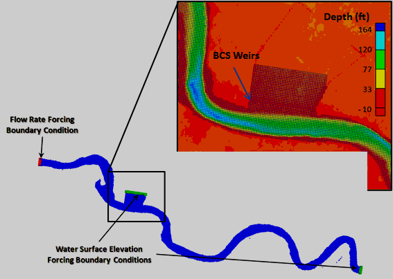
The 2-D CMS model domain was set to extend from the upstream gage at Reserve, which is about 8 miles upstream of the BCS, down to the Carrollton gage, which is south of New Orleans and about 27 miles downstream of the BCS. The domain is shown in Figure 4 and includes an expanded view in the vicinity of the BCS. The grid spacing was set to 196.8 ft (60 m). The river levees were used to delineate the boundary since they are expected to be slightly higher than the water elevations expected in the model simulations. The grid required 16,975 cells to cover the modeling domain.
The entrance area to the BCS was included in the model as well as a short section downstream of the spillway. Since the flow over the BCS was the main concern in the analysis, and the flow of the weirs is super-critical (no tail-water effects), the downstream section is only needed to provide an outlet for the flow and the model configuration for this area does not impact the results of the analysis. The weirs were assigned along a sequence of grid cells that coincide with the physical location of the BCS.
The grid extent was designed to coincide with gage locations so that measured data could be used as boundary conditions. Flow data from the Tarbert gage was used for the upstream flow boundary condition, and stage data from the Carrolton gage was used for the downstream water elevation boundary condition. A downstream water surface elevation for the extension of the spillway towards Lake Pontchartrain is also required, but the results of the analysis are not sensitive to the selection of this value. The value only needs to be sufficiently lower than the weir crest elevation to allow for supercritical flow over the weirs and high enough to keep the spillway submerged.
Three scenarios were selected for the model calibration and validation. The first two are high flow cases with the BCS closed. Data from March 9, 2001 was used for the calibration case and recorded stage. Flow from January 31, 2005 was used for validation of the model. The third calibration case used data from April 22, 2008 while a major flood event occurred and for which the BCS was opened. This case was used to validate the weir function in the CMS. For all cases, the calibration consisted of comparing the predicted stage at the Reserve gage. For Case 3, a comparison of the simulated and measured flow over the BCS was assessed.
The representation of the weirs in the model required special processing to ensure that the total length of the BCS weir system was correctly represented since the grid cells were longer than the individual BCS bays. The BCS contains 350 bays, each with a 20 ft (6.09 m) weir. Each bay is separated by a 2-foot thick wall, thus the total length of the spillway is 7,698 feet (when the last wall is not included). In order to simulate the operating conditions of the spillway bays, 40 cells were identified at the approximate location of the Bonnet Carre spillway. In order to correctly represent the total length of the BCS weirs in the model, each cell coincident with the BCS was assigned a total weir length equivalent to 8.75 bays, which is equivalent to 350 bays divided among 40 grid cells. Thus, each cell contained 175 feet of weir crest.
Another characteristic of the BCS bays is their alternating weir crest elevations. The bays are organized into seven sections. The length of each section, number of bays and weir crest elevations are shown in Table 2. The number of cells that were used to represent each section and the corresponding weir length are provided in the last two columns. The spillway sections are numbered from west to east:
Table 2. BCS Weir Configuration
| Section (numbered from west to east) | Number of Bays | Elevation of Weirs (ft) | Total BCS Weir Length in Section | Number of Grid Cells used for Each Section | Total Length (ft) of Weir Represented in Grid Cells |
| 1 | 44 | 17.22 | 880 | 5 | 875 |
| 2 | 43 | 15.35 | 860 | 5 | 875 |
| 3 | 44 | 17.22 | 880 | 5 | 875 |
| 4 | 88 | 15.35 | 1,720 | 10 | 1,750 |
| 5 | 44 | 17.22 | 880 | 5 | 875 |
| 6 | 43 | 15.35 | 860 | 5 | 875 |
| 7 | 44 | 17.22 | 880 | 5 | 875 |
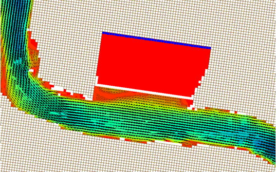
For Cases 1 and 2, the weir crest elevations were set to approximately 30 feet to insure that no flow passed through the spillway. The model calibration was obtained by globally adjusting the friction parameter (Manning’s n) until the model reproduced the measured upstream stage at the Reserve gage location. After a few simulations; the value of 0.019 was found to yield the best results. The velocity patterns in the vicinity of the spillway for Case 1 are shown in Figure 5. The model was then configured for the validation case (Case 2) to verify whether the model could reproduce good results for different stage and flow conditions. The results for these two cases are shown in Table 3.
Table 3. Model Calibration and Validation Results.
| Case ID | Type | Carrollton Stage (ft) (downstream boundary condition) | Tarbert Flow (cfs) (Upstream flow boundary) | Expected Reserve Stage (ft) | Simulated Reserve Stage (ft) | Percent Error |
| 1 | Calibration | 13.9 | 1,097,818 | 19.7 | 20.2 | 2.5 |
| 2 | Validation | 15.5 | 1,185,445 | 22.0 | 22.7 | 3.2 |
| 3 | Validation | 16.7 | 1,465,000 | 23.7 | 23.2 | 2.1 |
The final validation was completed for Case 3, which represents the flood event of 2008, and was used to calibrate the coefficients in the CMS weir representations. The 2008 flood report (URS, 2009), which documents the 2008 flood event, provides information on which bays of the BCS were open and the total flow through each bay. The total flow was estimated to be 167,000 cfs and 160 bays were opened. The total flow through the spillway in the simulation was 169,221 cfs using a weir coefficient of 0.57 and the stage results are shown in Table 3. The simulated velocity patterns for the flow through the spillway are shown in Figure 6. The effect on the staggered open bays is evident in the flow patterns.
Additional Information
This wiki technical note was prepared and funded under the Coastal Inlets Research Program (CIRP) being conducted at the U.S. Army Engineer Research and Development Center, Costal and Hydraulics Laboratory. Questions about this technical note can be addressed to to Dr. Christopher W. Reed (Chris_Reed@URSCorp.com) of URS Corporation, the CIRP Program Manager, Dr. Julie D. Rosati (Julie.D.Rosati@usace.army.mil), the assistant Program Manager, Dr. Nicholas C. Kraus (Nicholas.C.Kraus@usace.army.mil).
References
- Buttolph, A. M., C. W. Reed, N. C. Kraus, N. Ono, M. Larson, B. Camenen, H. Hanson, T. Wamsley, and A. . Zundel, A. K. 2006. Two-dimensional depth-averaged circulation model CMS-M2D: Version 3.0, Report 2, sediment transport and morphology change. Coastal and Hydraulics Laboratory Technical Report ERDC/CHL-TR-06-7. Vicksburg, MS: U.S. Army Engineer Research and Development Center.
- Militello, A., Reed, C.W., Zundel, A.K., and Kraus, N.C. 2004. Two-Dimensional Depth-Averaged Circulation Model M2D: Version 2.0, Report 1, Technical Documentation and User’s Guide, ERDC/CHL TR-04-2, U.S. Army Research and Development Center, Coastal and Hydraulics Laboratory, Vicksburg, MS.
- URS. 2009. Hydraulic Modeling of Proposed Container Facility Along Mississippi River at Bonnet Carre’ Spillway. URS Corporation, Tallahassee, FL.
- Villemonte, J.R (December 25,1947). "Submerged Weir Discharge Studies." Engineering News Record, p. 866-869.


