CMS-Flow:Non-equilibrium Sediment Transport: Difference between revisions
No edit summary |
|||
| Line 10: | Line 10: | ||
where the subscript <math>k</math> indicates the sediment size class, <math>h</math> is the total water depth (<math> h = \zeta + \eta </math>), <math>C_{tk} </math> is the total load concentration, <math>C_{t*k} </math> is the sediment transport capacity, <math>\beta _{tk}</math> is the total load correction factor, <math> \nu _s </math> is the diffusion coefficient, <math>r_{sk}</math> is the fraction of suspended sediments, <math>\alpha_t</math> is the total load adaptation coefficient, and <math>\omega_{sk}</math> is the sediment fall velocity. Equation (1) is valid for both single and mixed sediments. However, only single-size sediment transport is available through the SMS interface. To access the nonuniform sediment transport, Advanced Cards must be used. | where the subscript <math>k</math> indicates the sediment size class, <math>h</math> is the total water depth (<math> h = \zeta + \eta </math>), <math>C_{tk} </math> is the total load concentration, <math>C_{t*k} </math> is the sediment transport capacity, <math>\beta _{tk}</math> is the total load correction factor, <math> \nu _s </math> is the diffusion coefficient, <math>r_{sk}</math> is the fraction of suspended sediments, <math>\alpha_t</math> is the total load adaptation coefficient, and <math>\omega_{sk}</math> is the sediment fall velocity. Equation (1) is valid for both single and mixed sediments. However, only single-size sediment transport is available through the SMS interface. To access the nonuniform sediment transport, Advanced Cards must be used. | ||
== Transport Formula== | == Transport Formula == | ||
The concentration capacity may be calculated with either the Lund-CIRP (Carmenen and Larson 2007), the van Rijn (2007), or the Watanabe (1987) transport equations. The calculated sediment concentration capacities from these formula are multiplied by transport scaling factors which typically vary from 0.5-2.0 and have default value of 1.0. | The concentration capacity may be calculated with either the Lund-CIRP (Carmenen and Larson 2007), the van Rijn (2007), Soulsby-van Rijn (1997) or the Watanabe (1987) transport equations. The calculated sediment concentration capacities from these formula are multiplied by transport scaling factors which typically vary from 0.5-2.0 and have default value of 1.0. | ||
== Fall | == Fall Velocity == | ||
In CMS, the sediment fall velocity is calculated with the Soulsby-Whitehouse (1997) or Wu equation. If the sediment fall velocity has been measured in the laboratory, then it may be specified with the Advanced Card SEDIMENT_FALL_VELOCITY. It is not recommended to use the sediment fall velocity as a calibration parameter. | In CMS, the sediment fall velocity is calculated with the Soulsby-Whitehouse (1997) or Wu equation. If the sediment fall velocity has been measured in the laboratory, then it may be specified with the Advanced Card SEDIMENT_FALL_VELOCITY. It is not recommended to use the sediment fall velocity as a calibration parameter. | ||
Revision as of 17:11, 28 January 2011
UNDER CONSTRUCTION
written by Alejandro Sanchez Last date modified: December 8, 2010
Transport Equation
Non-cohesive sediment transport is calculated with a non-equilibrium bed-material (total load) formulation. In this approach, the suspended- and bed-load transport equations are combined into a single equation and thus there is one less empirical parameter to estimate (adaptation length). The transport equation is derived by adding the suspended- and bed-load transport equations to obtain the general sediment mass balance equation and then substituting a non-equilibrium expression for the bed elevation change as suggested by Wu (2004):
| (1) |
where the subscript indicates the sediment size class, is the total water depth (), is the total load concentration, is the sediment transport capacity, is the total load correction factor, is the diffusion coefficient, is the fraction of suspended sediments, is the total load adaptation coefficient, and is the sediment fall velocity. Equation (1) is valid for both single and mixed sediments. However, only single-size sediment transport is available through the SMS interface. To access the nonuniform sediment transport, Advanced Cards must be used.
Transport Formula
The concentration capacity may be calculated with either the Lund-CIRP (Carmenen and Larson 2007), the van Rijn (2007), Soulsby-van Rijn (1997) or the Watanabe (1987) transport equations. The calculated sediment concentration capacities from these formula are multiplied by transport scaling factors which typically vary from 0.5-2.0 and have default value of 1.0.
Fall Velocity
In CMS, the sediment fall velocity is calculated with the Soulsby-Whitehouse (1997) or Wu equation. If the sediment fall velocity has been measured in the laboratory, then it may be specified with the Advanced Card SEDIMENT_FALL_VELOCITY. It is not recommended to use the sediment fall velocity as a calibration parameter.
Total load correction factor
The total-load correction factor accounts for the time lag (hysteresis) between flow and sediment transport and is given by
| (2) |
where is the current depth-averaged current magnitude, is the bed-load transport velocity, and is the suspended-load correction factor defined by
| (3) |
where is the local sediment concentration, is the thickness of the bed-load layer, and is the stream-wise local current velocity. Assuming a logarithmic velocity distribution in non-dimensional form (shape function)
| (4) |
and an exponential concentration profile also in non-dimensional form
| (5) |
where is the local concentration, is a near-bottom concentration specified at a reference height , , , , and . Using (4) and (5) he analytical solution to (3) is
| (6) |
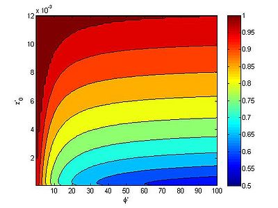
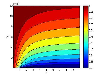
where is the exponential integral. Because the exponential integral requires and series expansion to solve it is more efficient to create a look up table and interpolate the values during the simulation which is what is done in CMS. A look up table is also created for when using the Rouse sediment concentration profile. Figure 1 and 2 compare the suspended load correction factor for exponential and Rouse sediment concentration profiles
In CMS, the bed load velocity is determined using the Van Rijn formula (1984)
| (4) |
where and is the non-dimensional transport stage number given by , and are empirical coefficients equal to 1.64 and 0.5 (Wu et al. 2006).
Bed Change Equation
The change in the water depth is calculated by
| (4) |
where is the sediment porosity, is the bed load transport, and is a bedslope coefficient.
Hiding and Exposure
Single-Sized Sediment Transport
At many sites, the bed material can be characterized by a single sediment size, with other sizes or materials (shell hash) which do not contribute significantly to morphology change, but do modify the sediment transport through hiding and exposure. By assuming that the spatial distribution of the bed material composition is constant in time, a hiding and exposure correction function can be introduced to correct the critical shields parameter where is the dimensionless hiding and exposure function and is the critical shear stress of the transport grain size. In CMS, a formula similar to that of Parker et al. (1995) and others is implemented where is the grain size corresponding to the 50th percentile, and is an empirical coefficient between 0.5-1.0 (default is 0.7).
The transport grain size is specified in the Advanced Card TRANSPORT_GRAIN_SIZE. The transport grain size should be the dominant grain size in the area of interest. To change the value of another Advanced Card HIDING_EXPOSURE_COEFFICIENT. If it is desired to test the model with a constant grain size and ignore the information in the D50_DATASET, the Advanced Card CONSTANT_GRAIN_SIZE.
Multiple-Sized Sediment Transport
For nonuniform sediments, the hiding and exposure is considered using a slightly modified form of the method proposed by Wu et al. (2000) which accounts information on the whole grain size distribution.
| (5) |
where and are the exposure and hiding probabilities calculated as
| (6) |
Bed Sorting and Gradation (nonuniform sediments)
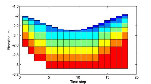
When simulating nonuniform sediments it is necessary to keep track of the vertical variation in bed composition. In order to do this, the bed is divided into discrete layers. The top layer is the mixing or active layer and is the layer of sediment which is actively being exchanged with the bed and suspended loads. The temporal variation of the bed-material in the mixing and second layers is calculated as (Wu 2004)
| (7) |
where and are the thicknesses of the mixing and second layers respectively. for or otherwise. Figure 3 shows an example of the bed layer evolution over time for varying bed deposition and erosion.
Avalanching
The process of avalanching is simulated by enforcing the angle of repose while maintaining mass continuity between adjacent cells. The presented approach adopts a relaxation method between adjacent cells and is stable and efficient. The equation for bed change due to avalanching is obtained by combining the equation of angle of repose and the continuity equation to obtain
| (8) |
where the subscripts p and i indicate the center and neighboring cells respectively, is the cell center distance between cells p and i, is the bed change due to avalanching, A is the cell area, is the bed slope, is the sediment repose angle, R is an under-relaxation factor (approximately 0.25-0.5), and and are the Heaviside and sign functions. The equation is applied every morphologic time step by sweeping through all of the computational cells to calculate and then modifying the bathymetry as .
Boundary Conditions
There are three types of boundary conditions in the sediment transport: Wet-dry, Outflow and Inflow.
1. Wet-dry interface.
- The interface between wet and dry cells has a zero-flux boundary condition. Both the advective and diffusive fluxes are set to zero at the wet-dry interfaces. Note that avalanching may still occur between wet-dry cells.
2. Outflow Boundary Condition
- Outflow boundaries are assigned a zero-gradient boundary condition and sediments are allowed to be transported freely out of the domain.
3. Inflow Boundary Condition
- When flow is entering the domain, it is necessary to specify the sediment concentration. In CMS-Flow, the inflow sediment concentration is set to the equilibrium sediment concentation. For some cases, it is desired to reduce the amount of sediment entering from the boundary such as in locations where the sediment source is limited (i.e. coral reefs). The inflow equilibrium sediment concentration may be adjusted by multiplying by a loading scaling factor and is specified by the Advanced Card NET_LOADING_FACTOR or SEDIMENT_INFLOW_LOADING_FACTOR.
Numerical Methods
The governing equations are discretized using the Finite Volume Method on a staggered, non-uniform Cartesian grid. Time integration is calculated with a simple explicit forward Euler scheme. Diffusion terms are discretized with the standard central difference scheme. Advection terms are discretized with either the first order upwind scheme or the second order Hybrid Linear/Parabolic Approximation (HLPA) scheme of Zhu (1991). The default advection scheme is HLPA but may be changed with the Advanced Card ADVECTION_SCHEME.
References
- Buttolph, A. M., C. W. Reed, N. C. Kraus, N. Ono, M. Larson, B. Camenen, H. Hanson, T. Wamsley, and A. K. Zundel. (2006). “Two-dimensional depth-averaged circulation model CMS-M2D: Version 3.0, Report 2: Sediment transport and morphology change.” Coastal and Hydraulics Laboratory Technical Report ERDC/CHL TR-06-9. Vicksburg, MS: U.S. Army Engineer Research and Development Center, U.S.A.
- Camenen, B., and Larson, M. (2007). “A unified sediment transport formulation for coastal inlet application”. Technical Report ERDC-CHL CR-07-01. Vicksburg, MS: U.S. Army Engineer Research and Development Center, U.S.A
- Parker, G., Kilingeman, P. C., and McLean, D. G. (1982). “Bed load and size distribution in paved gravel-bed streams.” J. Hydr. Div., ASCE, 108(4), 544-571.
- Soulsby, R. L. (1997). "Dynamics of marine sands, a manual for practical applications". H. R. Wallingford, UK: Thomas Telford.
- Watanabe, A. (1987). “3-dimensional numerical model of beach evolution”. Proc. Coastal Sediments ’87, ASCE, 802-817.
- Wu, W. (2004).“Depth-averaged 2-D numerical modeling of unsteady flow and nonuniform sediment transport in open channels”. J. Hydraulic Eng., ASCE, 135(10), 1013–1024.
- van Rijn, L. C. (1985). “Flume experiments of sedimentation in channels by currents and waves.” Report S 347-II, Delft Hydraulics laboratory, Deflt, Netherlands.
- Zhu, J. (1991). “A low diffusive and oscillation-free convection scheme”. Com. App. Num. Meth., 7, 225-232.
- Zundel, A. K. (2000). “Surface-water modeling system reference manual”. Brigham Young University, Environmental Modeling Research Laboratory, Provo, UT.
External Links
- Aug 2006 Two-Dimensional Depth-Averaged Circulation Model CMS-M2D: Version 3.0, Report 2, Sediment Transport and Morphology Change [1]
- Aug 2008 CMS-Wave: A Nearshore Spectral Wave Processes Model for Coastal Inlets and Navigation Projects [2]
Powerpoint presentation on NET
![{\displaystyle {\frac {\partial }{\partial t}}{\biggl (}{\frac {hC_{tk}}{\beta _{tk}}}{\biggr )}+{\frac {\partial (U_{j}hC_{tk})}{\partial x_{j}}}={\frac {\partial }{\partial x_{j}}}{\biggl [}\nu _{s}h{\frac {\partial (r_{sk}C_{tk})}{\partial x_{j}}}{\biggr ]}+\alpha _{t}\omega _{sk}(C_{t*k}-C_{tk})}](https://en.wikipedia.org/api/rest_v1/media/math/render/svg/a6c55af1889576378cdac2a528cdb87047fdef30)


![{\displaystyle \beta _{s}={\frac {E_{1}(\phi 'a')-E_{1}(\phi ')+\ln {(a'/z'_{0})}e^{-\phi 'a'}-\ln {(1/z'_{0})}e^{-\phi '}}{e^{-\phi 'a'}[\ln(1/z'_{0})-1][1-e^{-\phi '(1-a')}]}}}](https://en.wikipedia.org/api/rest_v1/media/math/render/svg/8295611498f2e3c78b9b5fc3aa12a8b128389a19)


![{\displaystyle (1-p'_{m}){\biggl (}{\frac {\partial \zeta }{\partial t}}{\biggr )}_{k}=\alpha _{t}\omega _{s}(C_{tk*}-C_{tk})+{\frac {\partial }{\partial x_{j}}}{\biggl [}D_{s}|Q_{bk}|{\frac {\partial \zeta }{\partial x_{j}}}{\biggr ]}}](https://en.wikipedia.org/api/rest_v1/media/math/render/svg/f96db6393c71df986eeb032c069bca0d96112a87)


