User Guide 005: Difference between revisions
No edit summary |
No edit summary |
||
| (17 intermediate revisions by the same user not shown) | |||
| Line 3: | Line 3: | ||
The Oceanweather format uses separate ASCII files to specify the wind speeds, atmospheric pressure and grid coordinates. The CMS-Flow cards used to specify the Oceanweather files are described below. | The Oceanweather format uses separate ASCII files to specify the wind speeds, atmospheric pressure and grid coordinates. The CMS-Flow cards used to specify the Oceanweather files are described below. | ||
Table 2-36. CMS-Flow cards used to specify the Oceanweather wind, atmospheric pressure and grid coordinates files. | |||
{|class="wikitable" | |||
|- | |||
!Card | |||
!Format | |||
!Notes | |||
|- | |||
|Oceanweather Wind File | |||
|[cards=OCEANWEATHER_WIND_FILE] | |||
[name=OWWndFile, type=char, | |||
default=none] | |||
|OWWndFile = Name of Oceanweather, Inc. wind file (*.win) | |||
|- | |||
|Oceanweather Atmospheric | |||
Pressure File | |||
|[cards=OCEANWEATHER_PRES_FILE] | |||
[name=OWPresFile, type=char, | |||
default=none] | |||
|OWPresFile = Name of Oceanweather, Inc. pressure file (*.pre) | |||
|- | |||
|Oceanweather Coordiante File |[cards=OCEANWEATHER_XY_FILE] | |||
[name=OWXYFile, type=char, | |||
default=none, | |||
optional=true] | |||
|OWXYFile = Name of Oceanweather, Inc. coordinate file (*.xy) | |||
|} | |||
Example 2-21. Excerpt of an Oceanweather wind file. | |||
---- | |||
Oceanweather WIN/PRE Format 2008090912 2008091406 | |||
iLat= 118iLong= 201DX=0.0150DY=0.0150SWLat=28.50000SWLon=-96.0000DT=200809091200 | |||
-4.8891 -4.8873 -4.8855 -4.8838 -4.8821 -4.8805 -4.8789 -4.8774 | |||
-4.8759 -4.8744 -4.8730 -4.8717 -4.8704 -4.8692 -4.8680 -4.8669 | |||
... | |||
-2.1530 -2.1382 -2.1233 -2.1085 -2.0937 -2.0788 -2.0637 -2.0486 | |||
-2.0335 -2.0184 -2.0035 -1.9887 -1.9741 -1.9598 -1.9458 -1.9322 | |||
-1.9190 -1.9062 -1.8938 -1.8820 -1.8707 -1.8600 | |||
iLat= 118iLong= 201DX=0.0150DY=0.0150SWLat=28.50000SWLon=-96.0000DT=200809091215 | |||
-4.9107 -4.9090 -4.9074 -4.9058 -4.9043 -4.9028 -4.9014 -4.9001 | |||
-4.8988 -4.8975 -4.8963 -4.8952 -4.8942 -4.8932 -4.8923 -4.8914 | |||
-4.8906 -4.8898 -4.8889 -4.8881 -4.8873 -4.8866 -4.8860 -4.8854 | |||
---- | |||
The last two arguments of the header are the starting and end times in yyyymmddhh. The wind data are preceded by a header line with the grid information. iLat and iLong are latitude North and longitude West. DX and DY are the grid spacing in units of degrees. SWLat and SWLon are the coordinates of the south-west grid point. DT is the actual time in yyyymmddhhMM. First the wind velocities in the x-direction are read then the velocities in the y-direction. The wind speeds are written in m/s. | The last two arguments of the header are the starting and end times in yyyymmddhh. The wind data are preceded by a header line with the grid information. iLat and iLong are latitude North and longitude West. DX and DY are the grid spacing in units of degrees. SWLat and SWLon are the coordinates of the south-west grid point. DT is the actual time in yyyymmddhhMM. First the wind velocities in the x-direction are read then the velocities in the y-direction. The wind speeds are written in m/s. | ||
Example 2 22. FORTRAN code for reading the Oceanweather Wind File. | |||
---- | |||
open(nunit,file=windfile,status='old') | |||
read(nunit,*) !skip header | |||
11 format(t6,i4,t16,i4) | |||
read(nunit,11) nwindi, nwindj | |||
backspace(nunit) | |||
!... | |||
13 format(68x,I4,4(I2)) | |||
read(nunit,13,end=333,err=333) iyear,imonth,iday,ihour,imin | |||
!... | |||
12 format(8f10.0) | |||
read(nunit,12,end=333,err=333) ((wndspdx(i,j),j=1,nwindj),i=1,nwindi) | |||
read(nunit,12,end=333,err=333) ((wndspdy(i,j),j=1,nwindj),i=1,nwindi) | |||
!... | |||
333 close(nunit) | |||
---- | |||
=Oceanweather Pressure File= | =Oceanweather Pressure File= | ||
| Line 15: | Line 75: | ||
The file format for the Oceanweather pressure file (*.pre) is best described with an example. | The file format for the Oceanweather pressure file (*.pre) is best described with an example. | ||
Example 2 23. Excerpt of an Oceanweather Pressure File. | |||
---- | |||
Oceanweather WIN/PRE Format 2008090912 2008091406 | |||
iLat= 118iLong= 201DX=0.0150DY=0.0150SWLat=28.50000SWLon=-96.0000DT=200809091200 | |||
1012.8565 1012.8564 1012.8563 1012.8563 1012.8563 1012.8563 1012.8563 1012.8564 | |||
1012.8583 1012.8587 1012.8591 1012.8596 1012.8600 1012.8605 1012.8610 1012.8616 | |||
... | |||
1014.2051 1014.2062 1014.2073 1014.2084 1014.2096 1014.2107 1014.2119 1014.2130 | |||
1014.2141 1014.2152 1014.2164 1014.2175 1014.2186 1014.2197 | |||
iLat= 118iLong= 201DX=0.0150DY=0.0150SWLat=28.50000SWLon=-96.0000DT=200809091215 | |||
1012.9089 1012.9089 1012.9089 1012.9089 1012.9090 1012.9091 1012.9092 1012.9094 | |||
1012.9095 1012.9098 1012.9100 1012.9103 1012.9106 1012.9109 1012.9113 1012.9117 | |||
---- | |||
The last two arguments of the header are the starting and end times in yyyymmddhh. The atmospheric pressure data (in units of mbar) is preceded by a header line with the grid information. iLat and iLong are latitude North and longitude West. DX and DY are the grid spacing in units of degrees. SWLat and SWLon are the coordinates of the south-west grid point. DT is the actual time in yyyymmddhhMM. | The last two arguments of the header are the starting and end times in yyyymmddhh. The atmospheric pressure data (in units of mbar) is preceded by a header line with the grid information. iLat and iLong are latitude North and longitude West. DX and DY are the grid spacing in units of degrees. SWLat and SWLon are the coordinates of the south-west grid point. DT is the actual time in yyyymmddhhMM. | ||
| Line 22: | Line 97: | ||
The file format for the Oceanweather coordinate file (*.xy) should contain the coordinates of the Oceanweather grid in the same coordinate system as the CMS-Flow grid. The order of the points should be from the south-west corner along each row. An example of an Oceanweather Coordinate File is shown below. | The file format for the Oceanweather coordinate file (*.xy) should contain the coordinates of the Oceanweather grid in the same coordinate system as the CMS-Flow grid. The order of the points should be from the south-west corner along each row. An example of an Oceanweather Coordinate File is shown below. | ||
---- | |||
903301.20526 77626.22617 | |||
904769.21902 77663.98766 | |||
906237.22790 77701.93744 | |||
907705.23188 77740.07550 | |||
909173.23093 77778.40184 | |||
910641.22504 77816.91646 | |||
---- | |||
| Line 39: | Line 125: | ||
[[File:fig_2-37.png]] | [[File:fig_2-37.png]] | ||
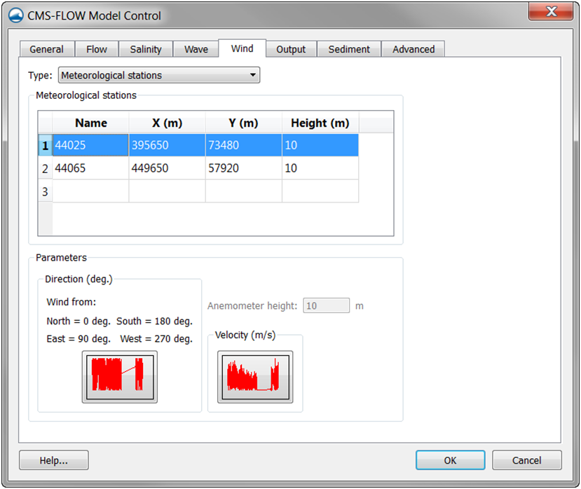
Figure 2 37. CMS-Flow Wind/Wave tab in the CMS-Flow Model Control window. | Figure 2-37. CMS-Flow Wind/Wave tab in the CMS-Flow Model Control window. | ||
Table 2-37. CMS-Flow card for specifying the reference frame. | |||
{|class="wikitable" | |||
|- | |||
!Input | |||
!Format | |||
!Notes | |||
|- | |||
|Meteorological Station Begin card | |||
|[card=MET_STA_BEGIN, | |||
version=4.1, block=MetStatBlock, | |||
childs=(NAME, WIND_INPUT_CURVE, | |||
COORDINATES, LATITUDE_LONGITUDE, | |||
WIND_VELOCITY_FACTOR, | |||
ANEMOMETER_HEIGHT, | |||
SMOOTHING_ITERATIONS, | |||
SMOOTHING_WIDTH, | |||
POWER_PARAMETER,MET_FILE)] | |||
|Starts the Meteorological Station Block | |||
|- | |||
|Name | |||
|[card=NAME] | |||
[arg=metsta%name, type=char, | |||
default=MPFile] | |||
[arg=WindPath, type=char] | |||
|Sets the name of the met station | |||
|- | |||
|Wind Input Curve | |||
|[card=WIND_CURVE] | |||
[arg=metsta%file, type=char] | |||
[arg=metsta%path, type=char] | |||
|File name and path of the spatially constant wind time series. | |||
|- | |||
|Coordinates | |||
|[card=COORDINATES] | |||
[arg=metsta%xsta, type=float] | |||
[arg=metsta%ysta, type=float] | |||
|Specifies the coordinates in local reference | |||
|- | |||
|Latitude / Longitude | |||
|[card=LATITUDE_LONGITUDE] | |||
[name=metsta%ylat, type=float] | |||
[name=metsta%xlon, type=float] | |||
|Specifies the coordinates in global coordinates | |||
|- | |||
|Wind Velocity Factor | |||
|[card=WIND_VELOCITY_FACTOR] | |||
[arg=metsta%wndfac, type=float, | |||
default=1.0] | |||
|Used to convert from different temporal averaging periods. | |||
|- | |||
|Anemometer Height | |||
|[card=ANEMOMETER_HEIGHT] | |||
[arg=metsta%wndht, type=float, | |||
units=m, default=10.0] | |||
[arg=metsta%path, type=char] | |||
|Defines the height of the anemometer in meters. | |||
|- | |||
|Smoothing | |||
Iterations | |||
|[card=SMOOTHING_ITERATIONS] | |||
[arg=metsta%ismoothiter, type=int, | |||
default=0] | |||
|Temporal smoothing iterations | |||
|- | |||
|Smoothing | |||
Width | |||
|[card=SMOOTHING_WIDTH] | |||
[arg=metsta%ismoothwidth, type=int, | |||
default=0, range=0 or odd] | |||
|Temporal smoothing window width. Must be odd number. | |||
|- | |||
|Power | |||
Parameter | |||
|[arg=POWER_PARAMETER] | |||
[arg=metsta%pow, type=float, | |||
range=1.0-5.0, default=1.0] | |||
|Power for Shepard interpolation. | |||
|- | |||
|Meteorological File name | |||
|[card=MET_FILE] | |||
[arg=metsta%file, type=char] | |||
|- | |||
|Meteorological Station End card | |||
|[card=MET_STA_END, | |||
version=4.1, block=MetStatBlock] | |||
|Ends the Meteorological Station Block | |||
|} | |||
Example 2-24. Specifying two meteorological stations. | |||
---- | |||
MET_STATION_BEGIN | |||
STATION_NAME 44065 | |||
COORDINATES 464000.0 53050.0 | |||
WIND_CURVE "Flow_mp.h5" "PROPERTIES/Model Params/Meteorological Stations/44065" | |||
ANEMOMETER_HEIGHT 10.0 m | |||
MET_STATION_END | |||
MET_STATION_BEGIN | |||
STATION_NAME 44025 !can be string, integer or floating | |||
COORDINATES 401490.0 93050.0 | |||
WIND_CURVE "Flow_mp.h5" "PROPERTIES/Model Params/Meteorological Stations/44025" | |||
ANEMOMETER_HEIGHT 10.0 m | |||
MET_STATION_END | |||
---- | |||
The wind components from meteorological stations is interpolated spatially using inverse-distance interpolation. A description of the interpolation procedure is provided in Appendix H. One advantage of the inverse-distance interpolation is the interpolation weights are independent of the interpolation function, and therefore only need to be calculated once and can be saved for computational efficiency. | The wind components from meteorological stations is interpolated spatially using inverse-distance interpolation. A description of the interpolation procedure is provided in Appendix H. One advantage of the inverse-distance interpolation is the interpolation weights are independent of the interpolation function, and therefore only need to be calculated once and can be saved for computational efficiency. | ||
| Line 51: | Line 240: | ||
Winds are specified in an Eulerian reference frame with respect to the solid earth. When the wind in the same direction of the currents the wind shear stress is lowered (Figure 2-38). When the wind and currents are in opposing directions, the wind shear stress is increased. For example, in the case of a current velocity of 1 m/s, with an opposing wind speed of 5 m/s, the Eulerian reference frame will give a surface stress proportional to (5 m/s)<sup>2</sup> = 25 m<sup>2</sup>/s<sup>2</sup>, while the Lagrangian reference frame will produce a surface proportional to (5-(-1) m/s)<sup>2</sup> = 36 m<sup>2</sup>/s<sup>2</sup>, which is an increase of 44%. | Winds are specified in an Eulerian reference frame with respect to the solid earth. When the wind in the same direction of the currents the wind shear stress is lowered (Figure 2-38). When the wind and currents are in opposing directions, the wind shear stress is increased. For example, in the case of a current velocity of 1 m/s, with an opposing wind speed of 5 m/s, the Eulerian reference frame will give a surface stress proportional to (5 m/s)<sup>2</sup> = 25 m<sup>2</sup>/s<sup>2</sup>, while the Lagrangian reference frame will produce a surface proportional to (5-(-1) m/s)<sup>2</sup> = 36 m<sup>2</sup>/s<sup>2</sup>, which is an increase of 44%. | ||
[[File:fig_2-38.png]] | |||
Figure 2-38. Schematic of wind and currents in same (left) and opposing directions (right). | |||
The wind reference frame is specified with the advanced card described in the table below. | The wind reference frame is specified with the advanced card described in the table below. | ||
table 2- | Table 2-38. CMS-Flow card for specifying the reference frame. | ||
{|class="wikitable" | |||
|- | |||
!Card | |||
!Arguments | |||
!Default | |||
!Options | |||
!Description | |||
|- | |||
|WIND_REFERENCE_FRAME | |||
|character | |||
|EULERIAN | |||
|EULERIAN | |||
LAGRANGIAN | |||
|Sets the reference frame for wind forcing | |||
|} | |||
Example 2 25. Wind reference frame specification. | |||
---- | |||
WIND_REFERENCE_FRAME LAGRANGIAN !{EULERIAN} | LAGRANGIAN | |||
---- | |||
=Notes= | |||
:• By default, the wind reference frame is set to Eulerian. It is recom-mended field applications to change the wind reference frame to Lagrangian. | |||
:• The Lagrangian reference frame is especially important for cases with high wind velocities such as storms. | |||
=Wind Drag Coefficient= | |||
The wind drag coefficient is calculated with the Hsu (1988) formula. The drag coefficient may be modified to scale the wind surface stress. The table below described the cards related to the wind drag coefficient. For further details on the wind drag coefficient see section ''Wind Surface Stress'' in the technical report. | |||
Table 2-39. CMS-Flow cards related to winds and atmospheric pressure | |||
{|class="wikitable" | |||
|- | |||
!Card | |||
!Arguments | |||
!Default | |||
!Range | |||
!Description | |||
|- | |||
|WIND_DRAG_COEFFICIENT | |||
|real | |||
|0.4 | |||
|>0 | |||
|kappa in Hsu (1988) formula for the wind drag coefficient. Scales the wind drag coefficient (Not the wind drag coefficient). | |||
|- | |||
|WIND_DRAG_SCALE_FACTOR | |||
|real | |||
|1.0 | |||
|0-1 | |||
|Scaling factor for the wind drag coefficient | |||
|} | |||
Example 2 26. Wind drag coefficient specification | |||
---- | |||
WIND_DRAG_COEFICIENT 0.4 !default = 0.4. Depreciated | |||
---- | |||
Example 2-27. Wind drag scale factor specification | |||
---- | |||
WIND_DRAG_COEFICIENT 1.0 !default = 1.0 | |||
---- | |||
=Anemometer Height= | |||
By default, the CMS assumes that the input wind velocities are specified at a 10-m height, if the height is different, the user may enter a different value as the Anemometer height. In SMS 11.0, the anemometer height is specified in the ''Wind/Wave'' tab of the ''CMS-Flow Model Control'' window. The wind velocities are internally converted to a 10-m reference height using the 1/7 rule (see Section <span style="color:#0000FF">Wind Surface Stress</span>). | |||
Table 2-40. CMS-Flow cards related to winds and atmospheric pressure | |||
{|class="wikitable" | |||
|- | |||
!Input | |||
!Format | |||
!Notes | |||
|- | |||
|Anemometer | |||
height | |||
|[cards=ANEMOMETER_HEIGHT] | |||
[name=WndHgt, type=float | |||
default=10.0, range=(WndHgt>0)] | |||
[name=WndHgtUnits, type=char, | |||
options=distUnits, default=’m’] | |||
|Height of wind speed | |||
|} | |||
Example 2-28. Anemometer height specification | |||
---- | |||
ANEMOMETER_HEIGHT 6.0 m !default = 10.0 m, Units optional | |||
---- | |||
=Wind Velocity Factor= | |||
The wind velocity factor may be used for converting the input wind velocity units or converting between different wind velocity definitions. Wind measurements are usually obtained as mean or “maximum sustained” wind in a certain time period. Generally, for hydrodynamic modeling mean wind speeds should be used (e.g. 10-min or 30-min averages). If winds are obtained as maximum sustained winds, they may be converted to averages using the wind velocity factor. Sustained wind speeds may be converted using the wind velocity factor. The wind velocity factor may be specified using an advanced card described in the table below. | The wind velocity factor may be used for converting the input wind velocity units or converting between different wind velocity definitions. Wind measurements are usually obtained as mean or “maximum sustained” wind in a certain time period. Generally, for hydrodynamic modeling mean wind speeds should be used (e.g. 10-min or 30-min averages). If winds are obtained as maximum sustained winds, they may be converted to averages using the wind velocity factor. Sustained wind speeds may be converted using the wind velocity factor. The wind velocity factor may be specified using an advanced card described in the table below. | ||
Table 2-41. CMS-Flow cards related to winds and atmospheric pressure | |||
{|class="wikitable" | |||
|- | |||
!Input | |||
!Format | |||
!Notes | |||
|- | |||
|Wind Velocity Factor | |||
|[cards=WIND_VELOCITY_FACTOR] | |||
[name=WndFac, type=float | |||
default=1.0, range=(WndFac>0)] | |||
|Specifies a wind velocity factor which directly multiplies by the input wind speeds. | |||
|} | |||
Example 2-29. Wind velocity factor specification | |||
---- | |||
WIND_VELOCITY_FACTOR 0.88 !Optional. default = 1.0 | |||
---- | |||
=Boundary Conditions= | |||
There are basically two types of lateral (horizontal) boundaries in CMS-Flow: closed and open. Closed boundaries are any boundary between wet and dry cells either at the edge or within the computational grid. Below is a summary of the boundary conditions available in CMS. | There are basically two types of lateral (horizontal) boundaries in CMS-Flow: closed and open. Closed boundaries are any boundary between wet and dry cells either at the edge or within the computational grid. Below is a summary of the boundary conditions available in CMS. | ||
The boundary condition types which indicate “advanced cards” are not implemented yet in the latest version of the interface (SMS 11.1) and therefore only available through the advanced cards. It is noted that the water level boundary conditions which are constant along the boundary may be corrected for the wind and wave forcing, or even spatial water level gradients may be added so that in fact the specified water level along the boundary is in general not constant. | :1. Wall (closed) | ||
:2. Flux (flux distributed along boundary) | |||
::a. Single flux value (advanced cards) | |||
::b. Single flux time-series | |||
:3. Water level | |||
::a. Constant along boundary | |||
:::(1) Single value (advanced cards) | |||
:::(2) Single time-series | |||
:::(3) Harmonic series | |||
:::(4) Tidal constituents | |||
:b. Variable along boundary | |||
:::(1) User-specified (advanced cards) | |||
:::(2) Extracted water levels from a larger domain simulation | |||
::::(a) Extracted using SMS | |||
::::(b) Automatically extracted in CMS (advanced cards) | |||
:::(3) Interpolated tidal constituents from a tidal database | |||
::::(a) Extracted using SMS | |||
::::(b) Automatically extracted in CMS (advanced cards) | |||
:4. Mixed water level and current velocity | |||
::a. Variable along boundary | |||
:::(1) User-specified (advanced cards) | |||
:::(2) Cross-shore boundary (approximate 1D solution) | |||
:::(3) Extracted water levels from a larger domain simulation | |||
::::(a) Using SMS | |||
::::(b) Using CMS (advanced cards) | |||
:::(4) Interpolated tidal constituents from a tidal database | |||
::::(a) Using SMS | |||
::::(b) Using CMS (advanced cards) | |||
The boundary condition types which indicate “advanced cards” are not implemented yet in the latest version of the interface (SMS 11.1) and therefore only available through the advanced cards. It is noted that the water level boundary conditions which are constant along the boundary may be corrected for the wind and wave forcing, or even spatial water level gradients may be added so that in fact the specified water level along the boundary is in general not constant. | |||
The implementation of the mixed water level and current velocity boundary conditions depends on the boundary condition type and the flow conditions. In the case of the cross-shore BC, a water level BC is applied when the flow is inwards of the simulation domain and a flux boundary condition is applied with the flow is outwards. For the other types BC’s the water level and current velocities are applied using the deferred correction approach for the implicit model. | The implementation of the mixed water level and current velocity boundary conditions depends on the boundary condition type and the flow conditions. In the case of the cross-shore BC, a water level BC is applied when the flow is inwards of the simulation domain and a flux boundary condition is applied with the flow is outwards. For the other types BC’s the water level and current velocities are applied using the deferred correction approach for the implicit model. | ||
Cellstrings | =Cellstrings= | ||
The spatial location of boundaries conditions is specified using cellstrings which are a series of cell ID’s corresponding to the boundary cells on the CMS-Flow grid. Once cellstrings have been created, boundary conditions can be assigned to the cellstring. Cellstrings without assigned boundary conditions or boundaries without cellstrings are assumed to be closed. | The spatial location of boundaries conditions is specified using cellstrings which are a series of cell ID’s corresponding to the boundary cells on the CMS-Flow grid. Once cellstrings have been created, boundary conditions can be assigned to the cellstring. Cellstrings without assigned boundary conditions or boundaries without cellstrings are assumed to be closed. | ||
Creating and Deleting Cellstrings | |||
=Creating and Deleting Cellstrings= | |||
When a CMS-Flow grid is generated, cellstrings are automatically generated along all of the boundaries. The user has the option to use any of these cellstrings or to create new cellstrings. Cell strings can either be manually created by clicking on the cells or by using the SMS interface to automatically detect and assign the cell strings. | When a CMS-Flow grid is generated, cellstrings are automatically generated along all of the boundaries. The user has the option to use any of these cellstrings or to create new cellstrings. Cell strings can either be manually created by clicking on the cells or by using the SMS interface to automatically detect and assign the cell strings. | ||
Manually Creating a Cellstring | |||
1. Select the Create cellstring tool | =Manually Creating a Cellstring= | ||
2. Single-click on the first cell of the cellstring. | |||
3. If necessary, single click on subsequent cells in the cellstring (around corners). | :1. Select the ''Create cellstring'' tool [[File:108-1.png]] . | ||
4. Double-click on the last cellstring to finish. | :2. Single-click on the first cell of the cellstring. | ||
:3. If necessary, single click on subsequent cells in the cellstring (around corners). | |||
:4. Double-click on the last cellstring to finish. | |||
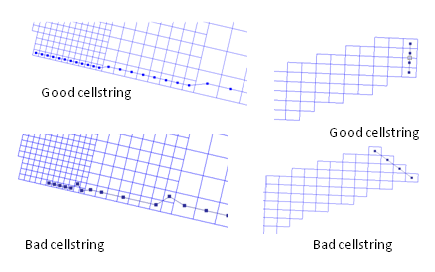
The figure below shows several examples of good and bad cellstrings. | The figure below shows several examples of good and bad cellstrings. | ||
[[File:fig_2-39.png]] | |||
Figure 2-39. Examples of good and bad boundary cellstrings. | |||
=Automatically Generate a Cellstring= | |||
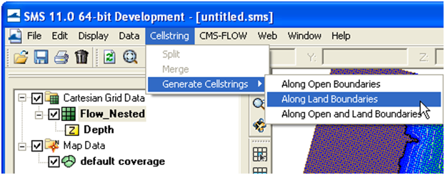
:1. Click on ''Cellstring | Generate Cellstrings'' and select one of the op-tions (Figure 2-40) | |||
::• ''Along Open Boundaries'' | |||
::• ''Along Land Boundaries'' | |||
::• ''Along Open and Land Boundaries'' | |||
[[File:fig_2-40.png]] | |||
Figure 2-40. Automated Cellstring generation in SMS 11.0 | |||
=Notes= | |||
:1. Cellstrings must be specified at boundaries. Internal boundaries are not allowed. | |||
:2. Cellstrings must be at least three cells wide. | |||
:3. Cellstrings must be specified at ALL open boundaries. Leaving any open boundaries without an assigned boundary will close that boundary and apply a wall boundary condition. | |||
:4. Land boundary conditions are not necessary at close boundaries (cells next to inactive cells). The CMS will automatically detect these land boundaries. | |||
:5. The orientation of cellstrings is important. Some inflow and all outflow boundary conditions assume a zero-gradient in the normal direction. If this assumption is not valid, the boundary may produce instability problems. It is recommended that the boundaries be placed in an orientation such that the spatial gradients normal to the cellstring or minimal. | |||
:6. Even though cell strings display along the cell centers, the actual boundary conditions are assigned at the cell faces. | |||
=Selecting Cellstrings= | |||
Once a boundary cellstring is created, the cell needs to be selected before assigning a boundary condition. If a cellstring is not selected, no boundary conditions can be assigned even if there is only one cellstring for the grid. There are basically two ways of selecting a cellstring in SMS. To assign this type of BC in SMS | |||
:1. Enable the cellstring selection tool by left-clicking on the ''Select a Cellstring'' button [[File:110-1.png]] in the ''Cartesian Module Toolbar''. | |||
:2. Select a cellstring by either | |||
::a. Right-clicking on a cellstring handle and select ''Assign BC'' (see left panel in the Figure below). | |||
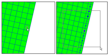
::b. Left-click and hold the button while dragging the mouse creating a selection box over the cellstring (see right panel of Figure 2-41). | |||
[[File:fig_2-41.png]] | |||
Figure 2-41. Selecting a celstring by either clicking on the cellstring handle (left) or dragging a selection box of the cellstring (right). | |||
=Deleting Cellstrings= | |||
To delete one or more cellstring | |||
:1. Select one or more cellstrings (see section ''Selecting Cellstrings'' for details). and open the ''CMS-Flow Boundary Conditions Window'' (see section <span style="color:#0000FF">Assigning a Boundary Condition</span> for details). | |||
:2. Either | |||
::a. While the cellstring is selected right-click anywhere on the t the cellstring and select Delete from the list of items in the pop-up menu (Figure 2-42). | |||
[[File:fig_2-42.png]] | |||
Figure 2-42. Deleting a cellstring by right-clicking on a cellstring and select Delete BC from the pop-up menu. | |||
2. | |||
::b. Press the ''Delete'' key, and then confirm the deletion in the pop-up window (see figure below). | |||
[[File:fig_2-43.png]] | |||
Figure 2-43. Deleting a cellstring in SMS by pressing the Delete key and selecting Yes in the pop-up window. | |||
a | |||
=Notes= | |||
:• The same procedure outlined above can be used to delete multiple cellstrings at once. | |||
=Tips= | |||
:• The SMS interface has the option to turn on or off the display of unse-lected cell strings. To change this option click on ''Display | Display Options'' or the ''Display Options Icon'' , and under the ''Cartesian Grid'' options, select the check box for ''Cellstrings'', and the appropriate boundary condition types. | |||
• The | |||
=Assigning Boundary Conditions= | |||
CMS-Flow has several types of boundary conditions which are listed and discussed below. The figure below shows the CMS-Flow Boundary Conditions Window in SMS. All CMS-Flow boundary conditions are forced at the edges of the domain by use of cellstrings defined with the Surface water Modelling System (SMS). Cellstrings can either be created manually or using the SMS tool called “Generate Along Boundary” which is found under the “Cellstring” menu. | CMS-Flow has several types of boundary conditions which are listed and discussed below. The figure below shows the CMS-Flow Boundary Conditions Window in SMS. All CMS-Flow boundary conditions are forced at the edges of the domain by use of cellstrings defined with the Surface water Modelling System (SMS). Cellstrings can either be created manually or using the SMS tool called “Generate Along Boundary” which is found under the “Cellstring” menu. | ||
Once a cellstring is selected, the boundary condition can be assigned in the ''CMS-Flow Boundary Conditions Window'' by | |||
:1. Select a cellstring (see ''Selecting Cellstrings'' section) | |||
:2. Open the ''CMS-Flow Boundary Conditions'' window by either | |||
::a. Right-clicking on a cellstring handle and selecting the Assign BC option (see Figure 2-44). | |||
[[File:fig_2-44.png]] | |||
Figure 2-44. Opening the CMS-Flow Boundary Conditions window by left clicking. | |||
::b. Click on the ''CMS-Flow'' menu, and select ''Assign BC'' (Figure 2-45). | |||
[[File:fig_2-45.png]] | |||
Figure 2-45. Opening the CMS-Flow Boundary Conditions Window through the CMS-Flow menu. | |||
An example view of the how the ''CMS-Flow Boundary Conditions Window'' is shown in Figure 2-46 below. The sections below describe in detail each type of boundary condition and the information required. | |||
[[File:fig_2-46.png]] | |||
Figure 2-46. CMS-Flow Boundary Conditions Window in SMS 11.0. | |||
Latest revision as of 17:24, 7 May 2015
Oceanweather Wind File
The Oceanweather format uses separate ASCII files to specify the wind speeds, atmospheric pressure and grid coordinates. The CMS-Flow cards used to specify the Oceanweather files are described below.
Table 2-36. CMS-Flow cards used to specify the Oceanweather wind, atmospheric pressure and grid coordinates files.
| Card | Format | Notes |
|---|---|---|
| Oceanweather Wind File | [cards=OCEANWEATHER_WIND_FILE]
[name=OWWndFile, type=char, default=none] |
OWWndFile = Name of Oceanweather, Inc. wind file (*.win) |
| Oceanweather Atmospheric
Pressure File |
[cards=OCEANWEATHER_PRES_FILE]
[name=OWPresFile, type=char, default=none] |
OWPresFile = Name of Oceanweather, Inc. pressure file (*.pre) |
| [cards=OCEANWEATHER_XY_FILE]
[name=OWXYFile, type=char, default=none, optional=true] |
OWXYFile = Name of Oceanweather, Inc. coordinate file (*.xy) |
Example 2-21. Excerpt of an Oceanweather wind file.
Oceanweather WIN/PRE Format 2008090912 2008091406
  iLat= 118iLong= 201DX=0.0150DY=0.0150SWLat=28.50000SWLon=-96.0000DT=200809091200
  -4.8891   -4.8873   -4.8855   -4.8838   -4.8821   -4.8805   -4.8789   -4.8774
  -4.8759   -4.8744   -4.8730   -4.8717   -4.8704   -4.8692   -4.8680   -4.8669
  ...
  -2.1530   -2.1382   -2.1233   -2.1085   -2.0937   -2.0788   -2.0637   -2.0486
  -2.0335   -2.0184   -2.0035   -1.9887   -1.9741   -1.9598   -1.9458   -1.9322
  -1.9190   -1.9062   -1.8938   -1.8820   -1.8707   -1.8600
  iLat= 118iLong= 201DX=0.0150DY=0.0150SWLat=28.50000SWLon=-96.0000DT=200809091215
  -4.9107   -4.9090   -4.9074   -4.9058   -4.9043   -4.9028   -4.9014   -4.9001
  -4.8988   -4.8975   -4.8963   -4.8952   -4.8942   -4.8932   -4.8923   -4.8914
  -4.8906   -4.8898   -4.8889   -4.8881   -4.8873   -4.8866   -4.8860   -4.8854
The last two arguments of the header are the starting and end times in yyyymmddhh. The wind data are preceded by a header line with the grid information. iLat and iLong are latitude North and longitude West. DX and DY are the grid spacing in units of degrees. SWLat and SWLon are the coordinates of the south-west grid point. DT is the actual time in yyyymmddhhMM. First the wind velocities in the x-direction are read then the velocities in the y-direction. The wind speeds are written in m/s.
Example 2 22. FORTRAN code for reading the Oceanweather Wind File.
open(nunit,file=windfile,status='old') read(nunit,*) !skip header 11 format(t6,i4,t16,i4) read(nunit,11) nwindi, nwindj backspace(nunit)
!...
13 format(68x,I4,4(I2)) read(nunit,13,end=333,err=333) iyear,imonth,iday,ihour,imin !... 12 format(8f10.0) read(nunit,12,end=333,err=333) ((wndspdx(i,j),j=1,nwindj),i=1,nwindi) read(nunit,12,end=333,err=333) ((wndspdy(i,j),j=1,nwindj),i=1,nwindi) !... 333 close(nunit)
Oceanweather Pressure File
The file format for the Oceanweather pressure file (*.pre) is best described with an example.
Example 2 23. Excerpt of an Oceanweather Pressure File.
Oceanweather WIN/PRE Format 2008090912 2008091406
 iLat= 118iLong= 201DX=0.0150DY=0.0150SWLat=28.50000SWLon=-96.0000DT=200809091200
 1012.8565 1012.8564 1012.8563 1012.8563 1012.8563 1012.8563 1012.8563 1012.8564
 1012.8583 1012.8587 1012.8591 1012.8596 1012.8600 1012.8605 1012.8610 1012.8616
 ...
 1014.2051 1014.2062 1014.2073 1014.2084 1014.2096 1014.2107 1014.2119 1014.2130
 1014.2141 1014.2152 1014.2164 1014.2175 1014.2186 1014.2197
 iLat= 118iLong= 201DX=0.0150DY=0.0150SWLat=28.50000SWLon=-96.0000DT=200809091215
 1012.9089 1012.9089 1012.9089 1012.9089 1012.9090 1012.9091 1012.9092 1012.9094
 1012.9095 1012.9098 1012.9100 1012.9103 1012.9106 1012.9109 1012.9113 1012.9117
The last two arguments of the header are the starting and end times in yyyymmddhh. The atmospheric pressure data (in units of mbar) is preceded by a header line with the grid information. iLat and iLong are latitude North and longitude West. DX and DY are the grid spacing in units of degrees. SWLat and SWLon are the coordinates of the south-west grid point. DT is the actual time in yyyymmddhhMM.
Oceanweather Coordinate File
The file format for the Oceanweather coordinate file (*.xy) should contain the coordinates of the Oceanweather grid in the same coordinate system as the CMS-Flow grid. The order of the points should be from the south-west corner along each row. An example of an Oceanweather Coordinate File is shown below.
903301.20526 77626.22617 904769.21902 77663.98766 906237.22790 77701.93744 907705.23188 77740.07550 909173.23093 77778.40184 910641.22504 77816.91646
Notes
- • The first column is the horizontal coordinate, and the second is the vertical coordinate.
- • The coordinates must be in the same coordinate as the CMS.
Tip
- • The easiest way to generate the Oceanweather Coordinate File is to make an ASCII file containing the coordinates in geographical coordi-nates, bring it into SMS, reproject on the CMS coordinate system and export the coordinates into a file to be used as the Oceanweather Coordinates File. A small Fortran program provided which converts the Oceanweather grid information to an *.xy file on the CIRP website: http://cirp.usace.army.mil/CIRPwiki/images/8/82/WINDLOC.rar
Meteorological Stations
Meteorological stations can be used to force the model. The locations of the stations are specified in the same coordinate system as the CMS-Flow (world coordinates). There are several options and parameters that can be set for each meteorological (met) station. The table below describes the CMS-Flow cards related to the met stations.
Figure 2-37. CMS-Flow Wind/Wave tab in the CMS-Flow Model Control window.
Table 2-37. CMS-Flow card for specifying the reference frame.
| Input | Format | Notes |
|---|---|---|
| Meteorological Station Begin card | [card=MET_STA_BEGIN,
version=4.1, block=MetStatBlock, childs=(NAME, WIND_INPUT_CURVE, COORDINATES, LATITUDE_LONGITUDE, WIND_VELOCITY_FACTOR, ANEMOMETER_HEIGHT, SMOOTHING_ITERATIONS, SMOOTHING_WIDTH, POWER_PARAMETER,MET_FILE)] |
Starts the Meteorological Station Block |
| Name | [card=NAME]
[arg=metsta%name, type=char, default=MPFile] [arg=WindPath, type=char] |
Sets the name of the met station |
| Wind Input Curve | [card=WIND_CURVE]
[arg=metsta%file, type=char] [arg=metsta%path, type=char] |
File name and path of the spatially constant wind time series. |
| Coordinates | [card=COORDINATES]
[arg=metsta%xsta, type=float] [arg=metsta%ysta, type=float] |
Specifies the coordinates in local reference |
| Latitude / Longitude | [card=LATITUDE_LONGITUDE]
[name=metsta%ylat, type=float] [name=metsta%xlon, type=float] |
Specifies the coordinates in global coordinates |
| Wind Velocity Factor | [card=WIND_VELOCITY_FACTOR]
[arg=metsta%wndfac, type=float, default=1.0] |
Used to convert from different temporal averaging periods. |
| Anemometer Height | [card=ANEMOMETER_HEIGHT]
[arg=metsta%wndht, type=float, units=m, default=10.0] [arg=metsta%path, type=char] |
Defines the height of the anemometer in meters. |
| Smoothing
Iterations |
[card=SMOOTHING_ITERATIONS]
[arg=metsta%ismoothiter, type=int, default=0] |
Temporal smoothing iterations |
| Smoothing
Width |
[card=SMOOTHING_WIDTH]
[arg=metsta%ismoothwidth, type=int, default=0, range=0 or odd] |
Temporal smoothing window width. Must be odd number. |
| Power
Parameter |
[arg=POWER_PARAMETER]
[arg=metsta%pow, type=float, range=1.0-5.0, default=1.0] |
Power for Shepard interpolation. |
| Meteorological File name | [card=MET_FILE]
[arg=metsta%file, type=char] | |
| Meteorological Station End card | [card=MET_STA_END,
version=4.1, block=MetStatBlock] |
Ends the Meteorological Station Block |
Example 2-24. Specifying two meteorological stations.
MET_STATION_BEGIN
 STATION_NAME       44065
 COORDINATES        464000.0 53050.0
 WIND_CURVE  "Flow_mp.h5" "PROPERTIES/Model Params/Meteorological Stations/44065"
 ANEMOMETER_HEIGHT  10.0 m
MET_STATION_END MET_STATION_BEGIN
 STATION_NAME       44025 !can be string, integer or floating
 COORDINATES        401490.0 93050.0
 WIND_CURVE  "Flow_mp.h5" "PROPERTIES/Model Params/Meteorological Stations/44025"
 ANEMOMETER_HEIGHT  10.0 m
MET_STATION_END
The wind components from meteorological stations is interpolated spatially using inverse-distance interpolation. A description of the interpolation procedure is provided in Appendix H. One advantage of the inverse-distance interpolation is the interpolation weights are independent of the interpolation function, and therefore only need to be calculated once and can be saved for computational efficiency.
Wind Reference Frames
Winds are specified in an Eulerian reference frame with respect to the solid earth. When the wind in the same direction of the currents the wind shear stress is lowered (Figure 2-38). When the wind and currents are in opposing directions, the wind shear stress is increased. For example, in the case of a current velocity of 1 m/s, with an opposing wind speed of 5 m/s, the Eulerian reference frame will give a surface stress proportional to (5 m/s)2 = 25 m2/s2, while the Lagrangian reference frame will produce a surface proportional to (5-(-1) m/s)2 = 36 m2/s2, which is an increase of 44%.
Figure 2-38. Schematic of wind and currents in same (left) and opposing directions (right).
The wind reference frame is specified with the advanced card described in the table below.
Table 2-38. CMS-Flow card for specifying the reference frame.
| Card | Arguments | Default | Options | Description |
|---|---|---|---|---|
| WIND_REFERENCE_FRAME | character | EULERIAN | EULERIAN
LAGRANGIAN |
Sets the reference frame for wind forcing |
Example 2 25. Wind reference frame specification.
WIND_REFERENCE_FRAME LAGRANGIAN !{EULERIAN} | LAGRANGIAN
Notes
- • By default, the wind reference frame is set to Eulerian. It is recom-mended field applications to change the wind reference frame to Lagrangian.
- • The Lagrangian reference frame is especially important for cases with high wind velocities such as storms.
Wind Drag Coefficient
The wind drag coefficient is calculated with the Hsu (1988) formula. The drag coefficient may be modified to scale the wind surface stress. The table below described the cards related to the wind drag coefficient. For further details on the wind drag coefficient see section Wind Surface Stress in the technical report.
Table 2-39. CMS-Flow cards related to winds and atmospheric pressure
| Card | Arguments | Default | Range | Description |
|---|---|---|---|---|
| WIND_DRAG_COEFFICIENT | real | 0.4 | >0 | kappa in Hsu (1988) formula for the wind drag coefficient. Scales the wind drag coefficient (Not the wind drag coefficient). |
| WIND_DRAG_SCALE_FACTOR | real | 1.0 | 0-1 | Scaling factor for the wind drag coefficient |
Example 2 26. Wind drag coefficient specification
WIND_DRAG_COEFICIENT 0.4 !default = 0.4. Depreciated
Example 2-27. Wind drag scale factor specification
WIND_DRAG_COEFICIENT 1.0 !default = 1.0
Anemometer Height
By default, the CMS assumes that the input wind velocities are specified at a 10-m height, if the height is different, the user may enter a different value as the Anemometer height. In SMS 11.0, the anemometer height is specified in the Wind/Wave tab of the CMS-Flow Model Control window. The wind velocities are internally converted to a 10-m reference height using the 1/7 rule (see Section Wind Surface Stress).
Table 2-40. CMS-Flow cards related to winds and atmospheric pressure
| Input | Format | Notes |
|---|---|---|
| Anemometer
height |
[cards=ANEMOMETER_HEIGHT]
[name=WndHgt, type=float default=10.0, range=(WndHgt>0)] [name=WndHgtUnits, type=char, options=distUnits, default=’m’] |
Height of wind speed |
Example 2-28. Anemometer height specification
ANEMOMETER_HEIGHT 6.0 m !default = 10.0 m, Units optional
Wind Velocity Factor
The wind velocity factor may be used for converting the input wind velocity units or converting between different wind velocity definitions. Wind measurements are usually obtained as mean or “maximum sustained” wind in a certain time period. Generally, for hydrodynamic modeling mean wind speeds should be used (e.g. 10-min or 30-min averages). If winds are obtained as maximum sustained winds, they may be converted to averages using the wind velocity factor. Sustained wind speeds may be converted using the wind velocity factor. The wind velocity factor may be specified using an advanced card described in the table below.
Table 2-41. CMS-Flow cards related to winds and atmospheric pressure
| Input | Format | Notes |
|---|---|---|
| Wind Velocity Factor | [cards=WIND_VELOCITY_FACTOR]
[name=WndFac, type=float default=1.0, range=(WndFac>0)] |
Specifies a wind velocity factor which directly multiplies by the input wind speeds. |
Example 2-29. Wind velocity factor specification
WIND_VELOCITY_FACTOR 0.88 !Optional. default = 1.0
Boundary Conditions
There are basically two types of lateral (horizontal) boundaries in CMS-Flow: closed and open. Closed boundaries are any boundary between wet and dry cells either at the edge or within the computational grid. Below is a summary of the boundary conditions available in CMS.
- 1. Wall (closed)
- 2. Flux (flux distributed along boundary)
- a. Single flux value (advanced cards)
- b. Single flux time-series
- 3. Water level
- a. Constant along boundary
- (1) Single value (advanced cards)
- (2) Single time-series
- (3) Harmonic series
- (4) Tidal constituents
- a. Constant along boundary
- b. Variable along boundary
- (1) User-specified (advanced cards)
- (2) Extracted water levels from a larger domain simulation
- (a) Extracted using SMS
- (b) Automatically extracted in CMS (advanced cards)
- (3) Interpolated tidal constituents from a tidal database
- (a) Extracted using SMS
- (b) Automatically extracted in CMS (advanced cards)
- 4. Mixed water level and current velocity
- a. Variable along boundary
- (1) User-specified (advanced cards)
- (2) Cross-shore boundary (approximate 1D solution)
- (3) Extracted water levels from a larger domain simulation
- (a) Using SMS
- (b) Using CMS (advanced cards)
- (4) Interpolated tidal constituents from a tidal database
- (a) Using SMS
- (b) Using CMS (advanced cards)
- a. Variable along boundary
The boundary condition types which indicate “advanced cards” are not implemented yet in the latest version of the interface (SMS 11.1) and therefore only available through the advanced cards. It is noted that the water level boundary conditions which are constant along the boundary may be corrected for the wind and wave forcing, or even spatial water level gradients may be added so that in fact the specified water level along the boundary is in general not constant.
The implementation of the mixed water level and current velocity boundary conditions depends on the boundary condition type and the flow conditions. In the case of the cross-shore BC, a water level BC is applied when the flow is inwards of the simulation domain and a flux boundary condition is applied with the flow is outwards. For the other types BC’s the water level and current velocities are applied using the deferred correction approach for the implicit model.
Cellstrings
The spatial location of boundaries conditions is specified using cellstrings which are a series of cell ID’s corresponding to the boundary cells on the CMS-Flow grid. Once cellstrings have been created, boundary conditions can be assigned to the cellstring. Cellstrings without assigned boundary conditions or boundaries without cellstrings are assumed to be closed.
Creating and Deleting Cellstrings
When a CMS-Flow grid is generated, cellstrings are automatically generated along all of the boundaries. The user has the option to use any of these cellstrings or to create new cellstrings. Cell strings can either be manually created by clicking on the cells or by using the SMS interface to automatically detect and assign the cell strings.
Manually Creating a Cellstring
- 1. Select the Create cellstring tool
 .
. - 2. Single-click on the first cell of the cellstring.
- 3. If necessary, single click on subsequent cells in the cellstring (around corners).
- 4. Double-click on the last cellstring to finish.
The figure below shows several examples of good and bad cellstrings.
Figure 2-39. Examples of good and bad boundary cellstrings.
Automatically Generate a Cellstring
- 1. Click on Cellstring | Generate Cellstrings and select one of the op-tions (Figure 2-40)
- • Along Open Boundaries
- • Along Land Boundaries
- • Along Open and Land Boundaries
Figure 2-40. Automated Cellstring generation in SMS 11.0
Notes
- 1. Cellstrings must be specified at boundaries. Internal boundaries are not allowed.
- 2. Cellstrings must be at least three cells wide.
- 3. Cellstrings must be specified at ALL open boundaries. Leaving any open boundaries without an assigned boundary will close that boundary and apply a wall boundary condition.
- 4. Land boundary conditions are not necessary at close boundaries (cells next to inactive cells). The CMS will automatically detect these land boundaries.
- 5. The orientation of cellstrings is important. Some inflow and all outflow boundary conditions assume a zero-gradient in the normal direction. If this assumption is not valid, the boundary may produce instability problems. It is recommended that the boundaries be placed in an orientation such that the spatial gradients normal to the cellstring or minimal.
- 6. Even though cell strings display along the cell centers, the actual boundary conditions are assigned at the cell faces.
Selecting Cellstrings
Once a boundary cellstring is created, the cell needs to be selected before assigning a boundary condition. If a cellstring is not selected, no boundary conditions can be assigned even if there is only one cellstring for the grid. There are basically two ways of selecting a cellstring in SMS. To assign this type of BC in SMS
- 1. Enable the cellstring selection tool by left-clicking on the Select a Cellstring button
 in the Cartesian Module Toolbar.
- 2. Select a cellstring by either
- a. Right-clicking on a cellstring handle and select Assign BC (see left panel in the Figure below).
- b. Left-click and hold the button while dragging the mouse creating a selection box over the cellstring (see right panel of Figure 2-41).
Figure 2-41. Selecting a celstring by either clicking on the cellstring handle (left) or dragging a selection box of the cellstring (right).
Deleting Cellstrings
To delete one or more cellstring
- 1. Select one or more cellstrings (see section Selecting Cellstrings for details). and open the CMS-Flow Boundary Conditions Window (see section Assigning a Boundary Condition for details).
- 2. Either
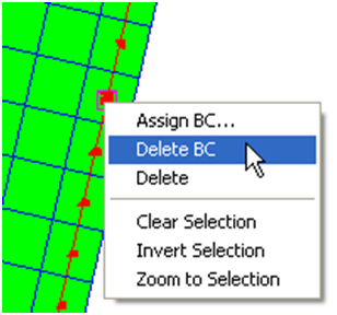
- a. While the cellstring is selected right-click anywhere on the t the cellstring and select Delete from the list of items in the pop-up menu (Figure 2-42).
Figure 2-42. Deleting a cellstring by right-clicking on a cellstring and select Delete BC from the pop-up menu.
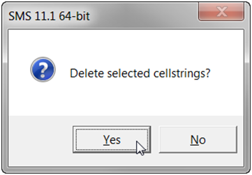
- b. Press the Delete key, and then confirm the deletion in the pop-up window (see figure below).
Figure 2-43. Deleting a cellstring in SMS by pressing the Delete key and selecting Yes in the pop-up window.
Notes
- • The same procedure outlined above can be used to delete multiple cellstrings at once.
Tips
- • The SMS interface has the option to turn on or off the display of unse-lected cell strings. To change this option click on Display | Display Options or the Display Options Icon , and under the Cartesian Grid options, select the check box for Cellstrings, and the appropriate boundary condition types.
Assigning Boundary Conditions
CMS-Flow has several types of boundary conditions which are listed and discussed below. The figure below shows the CMS-Flow Boundary Conditions Window in SMS. All CMS-Flow boundary conditions are forced at the edges of the domain by use of cellstrings defined with the Surface water Modelling System (SMS). Cellstrings can either be created manually or using the SMS tool called “Generate Along Boundary” which is found under the “Cellstring” menu.
Once a cellstring is selected, the boundary condition can be assigned in the CMS-Flow Boundary Conditions Window by
- 1. Select a cellstring (see Selecting Cellstrings section)
- 2. Open the CMS-Flow Boundary Conditions window by either
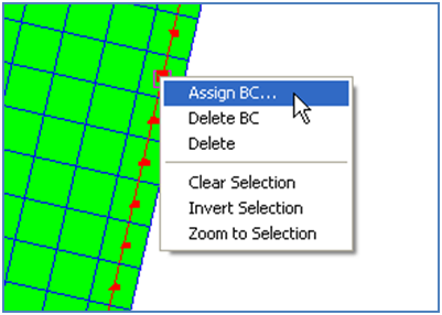
- a. Right-clicking on a cellstring handle and selecting the Assign BC option (see Figure 2-44).
Figure 2-44. Opening the CMS-Flow Boundary Conditions window by left clicking.
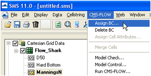
- b. Click on the CMS-Flow menu, and select Assign BC (Figure 2-45).
Figure 2-45. Opening the CMS-Flow Boundary Conditions Window through the CMS-Flow menu.
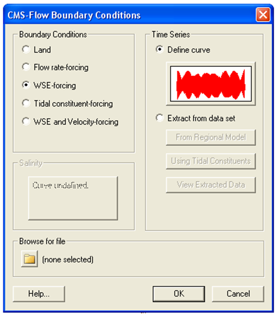
An example view of the how the CMS-Flow Boundary Conditions Window is shown in Figure 2-46 below. The sections below describe in detail each type of boundary condition and the information required.
Figure 2-46. CMS-Flow Boundary Conditions Window in SMS 11.0.
