Publications:CIRP-WN-12-1: Difference between revisions
No edit summary |
mNo edit summary |
||
| (53 intermediate revisions by 2 users not shown) | |||
| Line 1: | Line 1: | ||
< | {{DISPLAYTITLE:Inlet Reservoir Model: Part II: PC-Interface}} | ||
<p style="margin:0; background:#2580a2; font-size:20px; font-weight:bold; border:1px solid #a3bfb1; text-align:left; color:#FFF; padding:0.2em 0.4em;">CIRP-WN-12-1</p> | |||
= | <div style="text-align:left">'''''by Julie Dean Rosati, Mohamed Dabees, Wayne Tanner'''''</div><br> | ||
__TOC__ | |||
==PURPOSE== | |||
This Wiki-Coastal and Hydraulics Engineering Technical Note (Wiki-CHETN) is the second in the Inlet Reservoir CHETN series. This CHETN describes the Inlet Reservoir Model (IRM) interface and setting up an IRM project. Part III of the IRM series presents guidance for application and two example problems. The IRM calculates the time-dependent volumetric evolution of inlet morphologic features such as ebb and flood shoals, and estimates bypassing to adjacent beaches based on user-specified relationships (Kraus 2000, 2002). | This Wiki-Coastal and Hydraulics Engineering Technical Note (Wiki-CHETN) is the second in the Inlet Reservoir CHETN series. This CHETN describes the Inlet Reservoir Model (IRM) interface and setting up an IRM project. Part III of the IRM series presents guidance for application and two example problems. The IRM calculates the time-dependent volumetric evolution of inlet morphologic features such as ebb and flood shoals, and estimates bypassing to adjacent beaches based on user-specified relationships (Kraus 2000, 2002). | ||
==CITATION== | |||
Rosati, J.D., Dabees, M., and Tanner, W. 2011. Inlet Reservoir Model, Part II: PC-Interface. Coastal and <br> Hydraulics Engineering Technical Note ERDC/CHL CIRP-WN-12-1. Vicksburg, MS: U.S. Army Engineer Research <br> and Development Center. A pdf version of this document is available on the [http://cirp.usace.army.mil/products/?tab=5#products CIRP Website]. | |||
==INTRODUCTION== | |||
The Inlet Reservoir Model (IRM) calculates time-dependent sediment bypassing around an inlet and associated volume change for inlet morphologic features as identified by the user, as a function of longshore sediment transport along the adjacent beaches, user-defined equilibrium volumes for each morphologic feature, and engineering activities in vicinity of the inlet. In a typical wave-dominated inlet, there would be three distinct ocean-side morphologic features: an ebb shoal, bypassing bar, and an attachment bar. The concept of the Inlet Reservoir Model is based on the assumption that each feature has a maximum (equilibrium) sand-retention capacity that cannot be exceeded. Once a feature has reached capacity, all additional sediment transport to that feature will bypass to the next feature(s), until sediment arrives at the downdrift side of the inlet, or is deposited in another location such as the inlet channel or flood shoal. If a morphologic feature is partially full, it still provides partial bypassing. The Inlet Reservoir Model calculates growth of the shoals as a function of the littoral drift and equilibrium volumes of the shoals, and it accounts for the naturally long timescales of large morphologic features and time delays in exchange of material among the features. | The Inlet Reservoir Model (IRM) calculates time-dependent sediment bypassing around an inlet and associated volume change for inlet morphologic features as identified by the user, as a function of longshore sediment transport along the adjacent beaches, user-defined equilibrium volumes for each morphologic feature, and engineering activities in vicinity of the inlet. In a typical wave-dominated inlet, there would be three distinct ocean-side morphologic features: an ebb shoal, bypassing bar, and an attachment bar. The concept of the Inlet Reservoir Model is based on the assumption that each feature has a maximum (equilibrium) sand-retention capacity that cannot be exceeded. Once a feature has reached capacity, all additional sediment transport to that feature will bypass to the next feature(s), until sediment arrives at the downdrift side of the inlet, or is deposited in another location such as the inlet channel or flood shoal. If a morphologic feature is partially full, it still provides partial bypassing. The Inlet Reservoir Model calculates growth of the shoals as a function of the littoral drift and equilibrium volumes of the shoals, and it accounts for the naturally long timescales of large morphologic features and time delays in exchange of material among the features. | ||
| Line 20: | Line 19: | ||
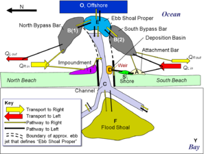
Figure 1 shows a schematic of an inlet system within the IRM with various types of reservoirs (e.g., channel, deposition basin) and morphologic features (e.g., ebb, flood shoal; bypassing bars). Identification of these features and the associated pathways can be estimated based on: | Figure 1 shows a schematic of an inlet system within the IRM with various types of reservoirs (e.g., channel, deposition basin) and morphologic features (e.g., ebb, flood shoal; bypassing bars). Identification of these features and the associated pathways can be estimated based on: | ||
* Shoreline position, bathymetric and topographic data to indicate shoals, impoundment areas and attachment bars; | |||
* Aerial photographs delineating wave breaking patterns, the typical extent and coverage of the ebb tidal jet, and sediment transport pathways as indicated by sand leaking through or around structures, and visible morphology such as subaqueous bars, etc.; | |||
* Knowledge of engineering activities within the inlet system (e.g., dredging of a deposition basin or dredged channel); | |||
* Knowledge of structural condition and layout (e.g., presence of a weir or degraded jetty, and segmentation or curvature of structure); and, | |||
* Previous studies documenting sediment budgets, magnitudes and directions of longshore sand transport rates, and approximate sand transport pathways. | |||
[[File:IRMPartIIFigure1.png|thumb|right|Figure 1. Schematic illustrating various reservoirs and morphologic features available in the IRM.]] | [[File:IRMPartIIFigure1.png|thumb|right|Figure 1. Schematic illustrating various reservoirs and morphologic features available in the IRM.]] | ||
Within the IRM, the Ebb shoal “proper,” | Within the IRM, the Ebb shoal “proper,” $E$, is defined as that portion of the ebb shoal that is directly within the ebb tidal jet, as indicated by a dashed line in Figure 1. The Bypassing bars, $B(1)$ and $B(2)$ are the portions of the ebb tidal shoal that are primarily influenced by wave-induced transport, and the Attachment bar, $A$, is the shore-attached feature that accretes in response to the wave reduction and delivery of sand provided by the Bypassing bar. It is important to realize that estimates of ebb shoal volumes documented in literature pertaining to a particular site most likely include the ebb shoal proper and bypassing bar. The IRM must delineate each morphologic feature to properly distinguish the temporal variation in growth and associated variation in bypassing. Part III of the IRM series discusses methods to estimate the relative volumes of these features, as well as the equilibrium volumes. | ||
As shown in Figure 1, sand transport pathways extend from the source (either transport towards the right (South Beach), $Q_{R in}$ or transport towards the left (North Beach), $Q_{L in}$ ) to associated features for which the user either defines or the IRM computes so-called “Coupling Coefficients.” Coupling Coefficients define the proportion of the incoming sand volume that will be transported to the destination feature. For example, in Figure 1, the user may define for a long-term average that 30% of $Q_{L in}$ is transported to the Impoundment feature adjacent to the north jetty, $I$, and the remaining 70% is transported to the North Bypassing Bar, $B(1)$. The Coupling Coefficient to $I$ would be 0.3, and the IRM would compute the Coupling Coefficient to $B(1)$ as 0.7. For other features with only one pathway, for example from $I$ to the Channel, $C$, the IRM calculates the Coupling Coefficient equal to 1.0. Other features in Figure 1 include a Shore accretion zone, $S$, which is fed by the Attachment bar, $A$; Deposition basin, $D$, inside the weir portion of the south jetty, which receives sand from the Shore, $S$; Flood shoal, $F$; and zones which only receive and are final “sinks” for sand, the Bay, $Y$, and Offshore, $O$. | |||
Once morphologic features, pathways, coupling coefficients, equilibrium volumes for each reservoir (discussed in a following section), and engineering activities such as dredging of the Channel, $C$, or Deposition basin, $D$, are defined, the IRM solves the governing equations that relate each feature's volume relative to its equilibrium volume and sand transport pathways into and out of each feature through time. | |||
''*Note: The IRM also allows the user to use different conventions for $Q_R$ and $Q_L$. The user may prefer to define $Q_R$ as “transport from the right beach,” and similarly for $Q_L$, “transport from the left beach.”'' | |||
==REVIEW OF THEORY== | |||
A brief review of the IRM concept and development is discussed to provide the reader basics of the underlying IRM assumptions. For more detail, the reader is referred to Kraus (2000, 2002). The underlying principles of the IRM are as follows (Kraus, 2000): | A brief review of the IRM concept and development is discussed to provide the reader basics of the underlying IRM assumptions. For more detail, the reader is referred to Kraus (2000, 2002). The underlying principles of the IRM are as follows (Kraus, 2000): | ||
# Mass (sand volume) is conserved. | |||
# Morphologic forms (reservoirs) and the sediment pathways among them can be identified, and the morphologic forms evolve while preserving identity. | |||
# Stable equilibrium of the individual aggregate morphologic forms exists. | |||
# Changes in meso- and macro-morphologic forms are reasonably smooth (e.g., these do not evolve abruptly). | |||
The IRM is conceptualized as a series of beakers, or reservoirs, that have a defined so-called “equilibrium” volume. Figure 2 shows how transport from left-to-right would be conceptualized with transport entering the inlet complex from the updrift beach, $Q_{in}$, and transporting to the Ebb shoal,$E$, then from $E$ to the Bypassing bar, $B$, then to the Attachment bar, $A$, and from there to the Shore, $S$. As the first reservoir in the system, $E$, fills and its volume increases closer to the equilibrium (identified for all features with a subscript “$e$”), $V_{Ee}$, it begins to increase the transport to the next reservoir, $B$, proportionally. Similarly, as $B$ fills towards its equilibrium, $V_{Be}$, it begins to transport more to $A$, and so on. | |||
[[File:IRMPartIIFigure2.png|thumb|right|Figure 2. Definition sketch for IRM (modified from Kraus, 2002)]] | |||
Equations for the Ebb shoal are presented below (modified from Kraus, 2002) to provide understanding of how the IRM is developed and explain the influence of the user-specified equilibrium volumes. For the full set of equations, the reader is directed to the CIRP Website and the [http://cirp.usace.army.mil/pubs/chetns/CHETN-IV-39.pdf CHETN-IV-39] publication. | |||
The amount of material bypassed from any of the morphological forms is assumed to vary in direct proportion to the volume of the form (amount of material in a given reservoir) at the time of the calculation. Therefore, the rate of sand leaving $E$, $Q_{Eout}$, is specified as, | |||
<big> | |||
\begin{equation} \tag{1} | |||
Q_{Eout}=\frac{V_E}{V_{Ee}}Q_{in} | |||
\end{equation} | |||
</big> | |||
in which $V_E$ is the volume of the ebb shoal at that time step, and $Q_{in}$ is taken to be constant (average annual rate). | |||
The | The mass balance equation governing the change in $V_E$ can be expressed as, | ||
< | <big> | ||
\begin{equation} \tag{2} | |||
\frac{dV_E}{dt}=Q_{in}-{Q_{Eout}} | |||
\end{equation} | |||
</big> | |||
where $t$ is time. Substituting Eqn. (1) into Eqn. (2), | |||
<big> | |||
\begin{equation} \tag{3} | |||
\frac{dV_E}{dt}=Q_{in}(1-\frac{V_E}{V_{Ee}}) | |||
\end{equation} | |||
</big> | |||
If this is a new inlet (not required by the IRM), then $V_E(0)=0$, and the solution of (3) is | |||
<big> | |||
\begin{equation} \tag{4} | |||
V_E=V_{Ee}(1-e^{-at}), a=\frac{Q_{in}}{V_{Ee}} | |||
\end{equation} | |||
</big> | |||
The parameter a defines a characteristic time scale for the ebb shoal. For example, if | The parameter a defines a characteristic time scale for the ebb shoal. For example, if $Q_{in} = 1 \times 10^5 m^3/$year and $V_{Ee} = 2 \times 10^6 m^3$, then $1/a = $ 20 years. The shoal is predicted to reach 50% and 95% of its equilibrium volume after 14 and 60 years, respectively, under the constant imposed transport rate. These timeframes are on the order of those associated with development of inlet ebb shoals. Using user-defined transport rates, pathways and equilibrium volumes, the IRM develops and solves a system of coupled equations that describe the time-dependent evolution of each reservoir. | ||
The significance of the equilibrium volume is apparent in the equations above. Larger reservoirs with greater equilibrium volumes will not bypass sand as rapidly as smaller reservoirs (Eqn. (1)). For the ebb shoal proper plus bypassing bars, the equilibrium volumes can be estimated by using Walton and Adams (1976) relationships, as discussed in Part III of the IRM series. For reservoirs that are total sinks for sand, such as | The significance of the equilibrium volume is apparent in the equations above. Larger reservoirs with greater equilibrium volumes will not bypass sand as rapidly as smaller reservoirs (Eqn. (1)). For the ebb shoal proper plus bypassing bars, the equilibrium volumes can be estimated by using Walton and Adams (1976) relationships, as discussed in Part III of the IRM series. For reservoirs that are total sinks for sand, such as $Y$ and $O$ (Figure 1), the user can set these equilibrium volumes to very large values. For sinks that are regularly dredged such as $C$ and $D$ (Figure 1), the equilibrium volumes can be set to a value which is representative of the typical dredging volume, which would imply that these reservoirs would not significantly bypass (or “leak”) sand until they begin to reach the typical dredging volume. Ideally, the user will have a history of growth and evolution of the Ebb shoal, Bypassing bars, Attachment bars, and other features with which to calibrate and validate the IRM for each project. | ||
==INTERFACE FEATURES== | |||
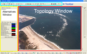
The IRM interface is a PC-based stand-alone program available for download from the CIRP website as discussed at the end of this CHETN. There are three main sections of the IRM interface, a Toolbar at the top of the page, an Alternatives window on the left-hand side, and the central Topology Window in which images can be displayed and the project formulated (Figure 3). The Toolbar and Alternative Window are discussed with reference to Figures 4 and 5. The Topology Window is discussed in the Example Problem. | The IRM interface is a PC-based stand-alone program available for download from the CIRP website as discussed at the end of this CHETN. There are three main sections of the IRM interface, a Toolbar at the top of the page, an Alternatives window on the left-hand side, and the central Topology Window in which images can be displayed and the project formulated (Figure 3). The Toolbar and Alternative Window are discussed with reference to Figures 4 and 5. The Topology Window is discussed in the Example Problem. | ||
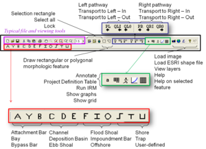
| Line 94: | Line 102: | ||
* The purple box shows typical file and viewing tools, such as save, cut, paste, etc. | |||
* Moving to the right, the next portion of the toolbar allows the user to select parts of the Topology window, all elements in the window, and lock a particular portion of the toolbar that will be repeated several times. For example, if several polygonal features were to be drawn in sequence, the lock and polygon would keep this feature active while drawing. Clicking again on the lock removes the lock. | |||
* The next section of the Toolbar allows the user to draw a rectangular or polygonal morphologic feature. Once selected, a drop-down menu appears with various features identified. Another way to create these morphologic features is to use the area identified with the red box at the bottom of the toolbar, as described at the bottom of Figure 4. Note that the size, shape, and alongshore extent of the user-defined features do not influence the equilibrium relationships in the IRM. The planview footprint of these features only facilitates visualization. | |||
* The area shown with a blue box on the Toolbar allows the user to draw pathways connecting transport rates to morphologic features, or feature-to-feature connections. The first section is for pathways to the left, '''PL''', and the next section is for pathways to the right. Immediately to the right of the “'''PL'''” is the option to draw an input transport flux towards the left, '''QLI''', and an output transport flux, '''QL0'''. Similarly, the next section allows pathways towards the right, '''PR''', input transport towards the right, '''QRI''', and an output flux towards the right, '''QR0'''. | |||
* The area shown in a green box on the Toolbar provides an option to annotate the Topology window, such as with names for features shown in an image, the date of an image, or other information. The project definition table summarizes information available about the project, and will be discussed later. When clicked, the runner button will execute the IRM for the conditions defined in the topology window, and the graphs (next icon) will change from a grayed-out image to a colored image when the run is completed. The user has the option to show a grid on the Topology window to better position and draw features. | |||
* Finally, the last portion of the Toolbar allows the user to load an image as background to the Topology window, whether it is a *.jpg or other image or a shape file. Clicking the Layer button allows the user to see the images that are loaded and to reorder which ones are visible. The last two buttons on the top Toolbar give information about IRM and provide help for specific features. | |||
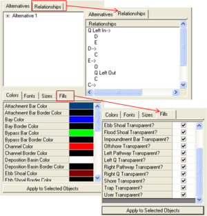
| Line 171: | Line 173: | ||
'''Step 6.''' To view the output, click on the graph icon and select which graphs to view. Figure 8 shows output from several transport and morphologic features. Dredging of the Channel and Deposition basin shows an effective “resetting” of these reservoirs, which then begin a new filling cycle. As would be expected, the output transport rate, | '''Step 6.''' To view the output, click on the graph icon and select which graphs to view. Figure 8 shows output from several transport and morphologic features. Dredging of the Channel and Deposition basin shows an effective “resetting” of these reservoirs, which then begin a new filling cycle. As would be expected, the output transport rate, $Q_{left out}$, increases with time as the ebb shoal and other morphologic features gain volume nearer to their equilibrium values. At the end of 100 years,$Q_{left out} = 40,000 m^3$ /year which is 25% of the incoming rate. | ||
| Line 190: | Line 192: | ||
[[File:IRMPartIIFigure9b.png|thumb|left|Figure 9b. Showing the graph for the ebb shoal, channel, flood shoal, and ebb shoal measurements]] | [[File:IRMPartIIFigure9b.png|thumb|left|Figure 9b. Showing the graph for the ebb shoal, channel, flood shoal, and ebb shoal measurements]] | ||
==CONCLUSIONS== | |||
The reservoir model of bypassing and ebb-shoal evolution requires input that is compatible with the amount and quality of data typically available in engineering and science studies. Such data are the longshore transport rate, which may be the net or gross rate depending on the inlet configuration; estimates of the equilibrium volumes of morphologic features; engineering activities during the period of interest; and qualitative understanding of sediment pathways at the particular inlet. The model predicts a delay in sand bypassing to the downdrift beach according to the properties of the morphologic system and longshore transport rate. The ratio of input longshore transport rate and equilibrium volume of the morphological feature is the main parameter governing volume change and bypassing rates. | The reservoir model of bypassing and ebb-shoal evolution requires input that is compatible with the amount and quality of data typically available in engineering and science studies. Such data are the longshore transport rate, which may be the net or gross rate depending on the inlet configuration; estimates of the equilibrium volumes of morphologic features; engineering activities during the period of interest; and qualitative understanding of sediment pathways at the particular inlet. The model predicts a delay in sand bypassing to the downdrift beach according to the properties of the morphologic system and longshore transport rate. The ratio of input longshore transport rate and equilibrium volume of the morphological feature is the main parameter governing volume change and bypassing rates. | ||
| Line 201: | Line 200: | ||
==AVAILABILITY== | |||
The IRM is available for download from the [http://cirp.usace.army.mil/products | The IRM is available for download from the CIRP Website [http://cirp.usace.army.mil/products/?tab=5 Inlet Reservoir Model Products page]. | ||
==POINT OF CONTACT== | |||
This Wiki-Note was prepared as part of the Coastal Inlets Research Program (CIRP) and was written by Dr. Julie D. Rosati (Julie.D.Rosati@usace.army.mil, Tel: 251-694-3719 Fax: 601-634-4314) of the U.S. Army Engineer Research and Development Center (ERDC), Coastal and Hydraulics Laboratory (CHL), 3909 Halls Ferry Road, Vicksburg, MS 39180; Dr. Mohamed Dabees, Humiston and Moore Engineers, Naples, FL; and Mr. Wayne Tanner, Applied Research Associates, Inc., Vicksburg, MS. Ms. Tanya Beck, Dr. Zeki Demirbilek, Ms. Ashley Frey, and Mr. Robert Thomas provided peer-review of this publication. For questions about this CHETN or information about the Coastal Inlets Research Program (CIRP), please contact the CIRP Program Manager, Dr. Rosati. | |||
==REFERENCES== | |||
* Dabees, M., and Kraus, N.C. 2004. Evaluation of ebb-tidal shoals as a Sand Source for Beach Nourishment: General Methodology with Reservoir Model Analysis. Proceedings, 17th National Conference on Beach Preservation Technology, CD-ROM, 21 p. | |||
* __________. 2005. General Methodology for Inlet Reservoir Model Analysis of Sand Management near Tidal Inlets. Proceedings Coastal Dynamics 2005, World Scientific, Inc., CD-ROM, 14 p. | |||
* __________. 2008. Cumulative Effects of Channel and Ebb Shoal Dredging on Inlet Evolution in Southwest Florida, USA. Proceedings 31st International Conference on Coastal Engineering, World Scientific, Inc., 2,303-2,315. | |||
* Kraus, N.C. 2000. Reservoir Model of Ebb-tidal Shoal Evolution and Sand Bypassing. J. Waterway, Port, Coastal, and Ocean Eng., 126(6), 305-313. | |||
* Kraus, N.C., 2002. Reservoir Model for Calculating Natural Sand Bypassing and Change in Volume of Ebb-Tidal Shoals, Part I: Description. Coastal Hydraulics Engineering Technical Note IV-39, Coastal Inlets Research Program, U.S. Army Research and Development Center, Coastal and Hydraulics Laboratory, Vicksburg, MS, 14 pp. | |||
* Zarillo, G.A., Kraus, N.C., and Hoeke, R.K. 2003. Morphologic Analysis of Sebastian Inlet, Florida: Enhancements to the Tidal Inlet Reservoir Model. Proc .Coastal Sediments ’03, CD-ROM, World Sci. Press and East Meets West Productions, Corpus Christi, TX ISBN-981-238-422-7, 14 p. | |||
<hr> | |||
[[Publications | Back to Publications]] | |||
[[category:Publication]] | |||
Latest revision as of 20:49, 25 August 2020
CIRP-WN-12-1
PURPOSE
This Wiki-Coastal and Hydraulics Engineering Technical Note (Wiki-CHETN) is the second in the Inlet Reservoir CHETN series. This CHETN describes the Inlet Reservoir Model (IRM) interface and setting up an IRM project. Part III of the IRM series presents guidance for application and two example problems. The IRM calculates the time-dependent volumetric evolution of inlet morphologic features such as ebb and flood shoals, and estimates bypassing to adjacent beaches based on user-specified relationships (Kraus 2000, 2002).
CITATION
 Rosati, J.D., Dabees, M., and Tanner, W. 2011. Inlet Reservoir Model, Part II: PC-Interface. Coastal and
 Hydraulics Engineering Technical Note ERDC/CHL CIRP-WN-12-1. Vicksburg, MS: U.S. Army Engineer Research
 and Development Center. A pdf version of this document is available on the CIRP Website.
INTRODUCTION
The Inlet Reservoir Model (IRM) calculates time-dependent sediment bypassing around an inlet and associated volume change for inlet morphologic features as identified by the user, as a function of longshore sediment transport along the adjacent beaches, user-defined equilibrium volumes for each morphologic feature, and engineering activities in vicinity of the inlet. In a typical wave-dominated inlet, there would be three distinct ocean-side morphologic features: an ebb shoal, bypassing bar, and an attachment bar. The concept of the Inlet Reservoir Model is based on the assumption that each feature has a maximum (equilibrium) sand-retention capacity that cannot be exceeded. Once a feature has reached capacity, all additional sediment transport to that feature will bypass to the next feature(s), until sediment arrives at the downdrift side of the inlet, or is deposited in another location such as the inlet channel or flood shoal. If a morphologic feature is partially full, it still provides partial bypassing. The Inlet Reservoir Model calculates growth of the shoals as a function of the littoral drift and equilibrium volumes of the shoals, and it accounts for the naturally long timescales of large morphologic features and time delays in exchange of material among the features.
Formulation of the IRM was discussed in Part I of the series, CHETN-IV-39 (Kraus 2002), for one-direction of net longshore transport from the up-drift beach through the ebb-tidal shoal, bypassing bar, attachment bar, to the downdrift beach. Capabilities of the IRM have expanded since the initial formulation to include transport in both directions, potential contributions of various engineering activities in proximity or certain distance of the inlet (such as dredging of channels, deposition basins, and mining of shoals); and the IRM can include as many morphologic features as the user defines. Previous studies that have used the IRM include Dabees and Kraus (2004, 2005, 2008); and Zarillo and Kraus (2003).
Figure 1 shows a schematic of an inlet system within the IRM with various types of reservoirs (e.g., channel, deposition basin) and morphologic features (e.g., ebb, flood shoal; bypassing bars). Identification of these features and the associated pathways can be estimated based on:
- Shoreline position, bathymetric and topographic data to indicate shoals, impoundment areas and attachment bars;
- Aerial photographs delineating wave breaking patterns, the typical extent and coverage of the ebb tidal jet, and sediment transport pathways as indicated by sand leaking through or around structures, and visible morphology such as subaqueous bars, etc.;
- Knowledge of engineering activities within the inlet system (e.g., dredging of a deposition basin or dredged channel);
- Knowledge of structural condition and layout (e.g., presence of a weir or degraded jetty, and segmentation or curvature of structure); and,
- Previous studies documenting sediment budgets, magnitudes and directions of longshore sand transport rates, and approximate sand transport pathways.
Within the IRM, the Ebb shoal “proper,” $E$, is defined as that portion of the ebb shoal that is directly within the ebb tidal jet, as indicated by a dashed line in Figure 1. The Bypassing bars, $B(1)$ and $B(2)$ are the portions of the ebb tidal shoal that are primarily influenced by wave-induced transport, and the Attachment bar, $A$, is the shore-attached feature that accretes in response to the wave reduction and delivery of sand provided by the Bypassing bar. It is important to realize that estimates of ebb shoal volumes documented in literature pertaining to a particular site most likely include the ebb shoal proper and bypassing bar. The IRM must delineate each morphologic feature to properly distinguish the temporal variation in growth and associated variation in bypassing. Part III of the IRM series discusses methods to estimate the relative volumes of these features, as well as the equilibrium volumes.
As shown in Figure 1, sand transport pathways extend from the source (either transport towards the right (South Beach), $Q_{R in}$ or transport towards the left (North Beach), $Q_{L in}$ ) to associated features for which the user either defines or the IRM computes so-called “Coupling Coefficients.” Coupling Coefficients define the proportion of the incoming sand volume that will be transported to the destination feature. For example, in Figure 1, the user may define for a long-term average that 30% of $Q_{L in}$ is transported to the Impoundment feature adjacent to the north jetty, $I$, and the remaining 70% is transported to the North Bypassing Bar, $B(1)$. The Coupling Coefficient to $I$ would be 0.3, and the IRM would compute the Coupling Coefficient to $B(1)$ as 0.7. For other features with only one pathway, for example from $I$ to the Channel, $C$, the IRM calculates the Coupling Coefficient equal to 1.0. Other features in Figure 1 include a Shore accretion zone, $S$, which is fed by the Attachment bar, $A$; Deposition basin, $D$, inside the weir portion of the south jetty, which receives sand from the Shore, $S$; Flood shoal, $F$; and zones which only receive and are final “sinks” for sand, the Bay, $Y$, and Offshore, $O$.
Once morphologic features, pathways, coupling coefficients, equilibrium volumes for each reservoir (discussed in a following section), and engineering activities such as dredging of the Channel, $C$, or Deposition basin, $D$, are defined, the IRM solves the governing equations that relate each feature's volume relative to its equilibrium volume and sand transport pathways into and out of each feature through time.
*Note: The IRM also allows the user to use different conventions for $Q_R$ and $Q_L$. The user may prefer to define $Q_R$ as “transport from the right beach,” and similarly for $Q_L$, “transport from the left beach.”
REVIEW OF THEORY
A brief review of the IRM concept and development is discussed to provide the reader basics of the underlying IRM assumptions. For more detail, the reader is referred to Kraus (2000, 2002). The underlying principles of the IRM are as follows (Kraus, 2000):
- Mass (sand volume) is conserved.
- Morphologic forms (reservoirs) and the sediment pathways among them can be identified, and the morphologic forms evolve while preserving identity.
- Stable equilibrium of the individual aggregate morphologic forms exists.
- Changes in meso- and macro-morphologic forms are reasonably smooth (e.g., these do not evolve abruptly).
The IRM is conceptualized as a series of beakers, or reservoirs, that have a defined so-called “equilibrium” volume. Figure 2 shows how transport from left-to-right would be conceptualized with transport entering the inlet complex from the updrift beach, $Q_{in}$, and transporting to the Ebb shoal,$E$, then from $E$ to the Bypassing bar, $B$, then to the Attachment bar, $A$, and from there to the Shore, $S$. As the first reservoir in the system, $E$, fills and its volume increases closer to the equilibrium (identified for all features with a subscript “$e$”), $V_{Ee}$, it begins to increase the transport to the next reservoir, $B$, proportionally. Similarly, as $B$ fills towards its equilibrium, $V_{Be}$, it begins to transport more to $A$, and so on.

Equations for the Ebb shoal are presented below (modified from Kraus, 2002) to provide understanding of how the IRM is developed and explain the influence of the user-specified equilibrium volumes. For the full set of equations, the reader is directed to the CIRP Website and the CHETN-IV-39 publication.
The amount of material bypassed from any of the morphological forms is assumed to vary in direct proportion to the volume of the form (amount of material in a given reservoir) at the time of the calculation. Therefore, the rate of sand leaving $E$, $Q_{Eout}$, is specified as,
\begin{equation} \tag{1}
Q_{Eout}=\frac{V_E}{V_{Ee}}Q_{in}
\end{equation}
in which $V_E$ is the volume of the ebb shoal at that time step, and $Q_{in}$ is taken to be constant (average annual rate).
The mass balance equation governing the change in $V_E$ can be expressed as,
\begin{equation} \tag{2}
\frac{dV_E}{dt}=Q_{in}-{Q_{Eout}}
\end{equation}
where $t$ is time. Substituting Eqn. (1) into Eqn. (2),
\begin{equation} \tag{3}
\frac{dV_E}{dt}=Q_{in}(1-\frac{V_E}{V_{Ee}})
\end{equation}
If this is a new inlet (not required by the IRM), then $V_E(0)=0$, and the solution of (3) is
\begin{equation} \tag{4}
V_E=V_{Ee}(1-e^{-at}), a=\frac{Q_{in}}{V_{Ee}}
\end{equation}
The parameter a defines a characteristic time scale for the ebb shoal. For example, if $Q_{in} = 1 \times 10^5 m^3/$year and $V_{Ee} = 2 \times 10^6 m^3$, then $1/a = $ 20 years. The shoal is predicted to reach 50% and 95% of its equilibrium volume after 14 and 60 years, respectively, under the constant imposed transport rate. These timeframes are on the order of those associated with development of inlet ebb shoals. Using user-defined transport rates, pathways and equilibrium volumes, the IRM develops and solves a system of coupled equations that describe the time-dependent evolution of each reservoir.
The significance of the equilibrium volume is apparent in the equations above. Larger reservoirs with greater equilibrium volumes will not bypass sand as rapidly as smaller reservoirs (Eqn. (1)). For the ebb shoal proper plus bypassing bars, the equilibrium volumes can be estimated by using Walton and Adams (1976) relationships, as discussed in Part III of the IRM series. For reservoirs that are total sinks for sand, such as $Y$ and $O$ (Figure 1), the user can set these equilibrium volumes to very large values. For sinks that are regularly dredged such as $C$ and $D$ (Figure 1), the equilibrium volumes can be set to a value which is representative of the typical dredging volume, which would imply that these reservoirs would not significantly bypass (or “leak”) sand until they begin to reach the typical dredging volume. Ideally, the user will have a history of growth and evolution of the Ebb shoal, Bypassing bars, Attachment bars, and other features with which to calibrate and validate the IRM for each project.
INTERFACE FEATURES
The IRM interface is a PC-based stand-alone program available for download from the CIRP website as discussed at the end of this CHETN. There are three main sections of the IRM interface, a Toolbar at the top of the page, an Alternatives window on the left-hand side, and the central Topology Window in which images can be displayed and the project formulated (Figure 3). The Toolbar and Alternative Window are discussed with reference to Figures 4 and 5. The Topology Window is discussed in the Example Problem.
The top Toolbar is shown in the top-central portion of Figure 4, with a black rectangle outline. From left to right, each of these features is described below.
- The purple box shows typical file and viewing tools, such as save, cut, paste, etc.
- Moving to the right, the next portion of the toolbar allows the user to select parts of the Topology window, all elements in the window, and lock a particular portion of the toolbar that will be repeated several times. For example, if several polygonal features were to be drawn in sequence, the lock and polygon would keep this feature active while drawing. Clicking again on the lock removes the lock.
- The next section of the Toolbar allows the user to draw a rectangular or polygonal morphologic feature. Once selected, a drop-down menu appears with various features identified. Another way to create these morphologic features is to use the area identified with the red box at the bottom of the toolbar, as described at the bottom of Figure 4. Note that the size, shape, and alongshore extent of the user-defined features do not influence the equilibrium relationships in the IRM. The planview footprint of these features only facilitates visualization.
- The area shown with a blue box on the Toolbar allows the user to draw pathways connecting transport rates to morphologic features, or feature-to-feature connections. The first section is for pathways to the left, PL, and the next section is for pathways to the right. Immediately to the right of the “PL” is the option to draw an input transport flux towards the left, QLI, and an output transport flux, QL0. Similarly, the next section allows pathways towards the right, PR, input transport towards the right, QRI, and an output flux towards the right, QR0.
- The area shown in a green box on the Toolbar provides an option to annotate the Topology window, such as with names for features shown in an image, the date of an image, or other information. The project definition table summarizes information available about the project, and will be discussed later. When clicked, the runner button will execute the IRM for the conditions defined in the topology window, and the graphs (next icon) will change from a grayed-out image to a colored image when the run is completed. The user has the option to show a grid on the Topology window to better position and draw features.
- Finally, the last portion of the Toolbar allows the user to load an image as background to the Topology window, whether it is a *.jpg or other image or a shape file. Clicking the Layer button allows the user to see the images that are loaded and to reorder which ones are visible. The last two buttons on the top Toolbar give information about IRM and provide help for specific features.
The Alternatives window is shown in Figure 5, and allows the user to view and edit the Topology Window. Right-click on an existing Alternative in this window to copy the IRM file into a duplicate Alternative #2. In this way an original set up can be altered with different pathways, engineering activities, or transport rates and differences readily viewed. The relationships between each morphologic feature can be viewed in the Relationships tab. Finally, fonts, colors and transparencies of features can be altered at the bottom of the window. Change colors and fonts, then select the features that are to be modified by using the selection buttons. Then click on “Apply to Selected Objects” to have the changes implemented.
In this section, a simple example for Rudee Inlet, Virginia is set up with hypothetical data to illustrate operation of the IRM and highlight features of the IRM interface, particularly use of the Topology Window. Part III of the IRM CHETN series applies the IRM to two other project sites to provide additional guidance on how to estimate quantities and pathways.
EXAMPLE, RUDEE INLET, VIRGINIA. When the IRM is installed, it creates a directory with two example cases, one for Sebastian Inlet, Florida and the other for Rudee Inlet.
Step 1. Load the image for Rudee Inlet as background in the Topology Window by clicking on the camera in the upper toolbar, and browsing for the file “RudeeInlet comp.jpg.” If the IRM was installed in the default directory, this image will be located at C:\Program Files\USACE\Reservoir\Data. Once the image is loaded, the user can click on the Layer button to see the path to any images that are loaded and reorder which image is visible, for multiple overlapping images. The user can save the file as “ExampleRudee.rsv” (all IRM files are automatically saved with a *.rsv extension).
Step 2. Rudee Inlet has a weir jetty on the south (right) side of the image, with a deposition basin inside the weir jetty which is regularly dredged. Net longshore sand transport (LST) is from right to left. First, draw the primary LST pathway by choosing the “transport to the left, into the system,” QLI button, and clicking and dragging the extent of this arrow coming into the south weir; double-click to end the arrow. Similarly, draw the “transport to the left, out of the system”, QLO button. These two buttons are now grayed-out in the upper toolbar.
Step 3. Now begin drawing morphologic features within the inlet system. Select “Draw polygonal feature" and choose a Depositional basin to draw inside the weir section of the project. Continue drawing each morphologic feature, including the channel, ebb shoal, an offshore zone, flood shoal, and bay (Figure 6). If indices of a particular morphologic feature need to be moved, click on the feature and drag one of the corners (see ebb shoal in Figure 6 showing an indices being repositioned).
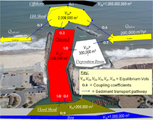
Step 4. The next step is to draw transport pathways towards the left. The transport pathways should represent the directions sediment is transported in and around the inlet when transport is directed to the left. Select “Draw left pathway,” and begin dragging and double-clicking to create each pathway. Multiple pathways can extend from QLI, QLO, and any morphologic feature. Once the PL button has been clicked that it remains locked; to unlock it, click on the lock button twice. Pathways can be directed to the right, onshore, and offshore for conditions in which inlet processes cause local reversals of sediment that originated from the QLI source (Figure 6).
Step 5. The best way to enter data within the IRM is to double-click on the transport flux, pathway, or morphologic feature of interest and populate each data tab. To begin, double-click on Qleft in and enter the transport rate shown in Figure 6. Data can be entered for the remaining morphologic features and pathways as shown in Figure 6 by double-clicking on each. Note that the sum of all pathways exiting a morphologic feature or transport flux must equal 1.0.
Click on the Project Definition button to see the data that has been entered. The default time period for the IRM is to begin in 1900 and run for 100 years, until 2000. Next add in the engineering activities for the Deposition basin and Channel as shown in Table 1. Double-click on the Deposition basin and Channel and enter these data into the Events tab.
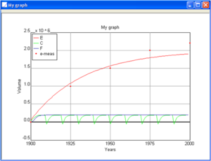
Measured data can be entered by double-clicking on a morphologic feature and selecting the Measurements tab. Add additional rows using the Add Row button at the bottom of the menu. Figure 7 shows hypothetical Ebb shoal volume measurements.
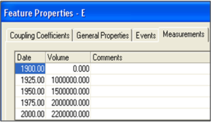
Once all data have been entered, click on the runner button in the top toolbar and let the program calculate. The run is completed when the graph icon becomes active.
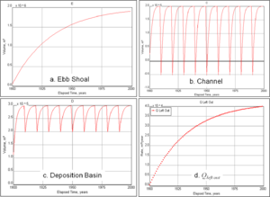
Step 6. To view the output, click on the graph icon and select which graphs to view. Figure 8 shows output from several transport and morphologic features. Dredging of the Channel and Deposition basin shows an effective “resetting” of these reservoirs, which then begin a new filling cycle. As would be expected, the output transport rate, $Q_{left out}$, increases with time as the ebb shoal and other morphologic features gain volume nearer to their equilibrium values. At the end of 100 years,$Q_{left out} = 40,000 m^3$ /year which is 25% of the incoming rate.
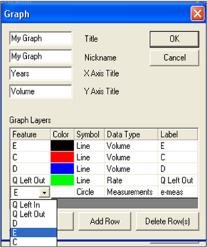
User-specified graphs can be created by combining multiple output types. In the graph menu, select Add Graph, add a title and axis labels, then add features by clicking Add Row then using the drop-down menu to add the feature of interest (Figure 9a). If measured data are available, add these by selecting Data Type as “Measurements,” selecting the morphologic feature for which there are data, and selecting the desired symbol (Figure 9b).
CONCLUSIONS
The reservoir model of bypassing and ebb-shoal evolution requires input that is compatible with the amount and quality of data typically available in engineering and science studies. Such data are the longshore transport rate, which may be the net or gross rate depending on the inlet configuration; estimates of the equilibrium volumes of morphologic features; engineering activities during the period of interest; and qualitative understanding of sediment pathways at the particular inlet. The model predicts a delay in sand bypassing to the downdrift beach according to the properties of the morphologic system and longshore transport rate. The ratio of input longshore transport rate and equilibrium volume of the morphological feature is the main parameter governing volume change and bypassing rates.
Part III of the IRM series discusses estimating input values and use of the IRM with project case studies.
AVAILABILITY
The IRM is available for download from the CIRP Website Inlet Reservoir Model Products page.
POINT OF CONTACT
This Wiki-Note was prepared as part of the Coastal Inlets Research Program (CIRP) and was written by Dr. Julie D. Rosati (Julie.D.Rosati@usace.army.mil, Tel: 251-694-3719 Fax: 601-634-4314) of the U.S. Army Engineer Research and Development Center (ERDC), Coastal and Hydraulics Laboratory (CHL), 3909 Halls Ferry Road, Vicksburg, MS 39180; Dr. Mohamed Dabees, Humiston and Moore Engineers, Naples, FL; and Mr. Wayne Tanner, Applied Research Associates, Inc., Vicksburg, MS. Ms. Tanya Beck, Dr. Zeki Demirbilek, Ms. Ashley Frey, and Mr. Robert Thomas provided peer-review of this publication. For questions about this CHETN or information about the Coastal Inlets Research Program (CIRP), please contact the CIRP Program Manager, Dr. Rosati.
REFERENCES
- Dabees, M., and Kraus, N.C. 2004. Evaluation of ebb-tidal shoals as a Sand Source for Beach Nourishment: General Methodology with Reservoir Model Analysis. Proceedings, 17th National Conference on Beach Preservation Technology, CD-ROM, 21 p.
- __________. 2005. General Methodology for Inlet Reservoir Model Analysis of Sand Management near Tidal Inlets. Proceedings Coastal Dynamics 2005, World Scientific, Inc., CD-ROM, 14 p.
- __________. 2008. Cumulative Effects of Channel and Ebb Shoal Dredging on Inlet Evolution in Southwest Florida, USA. Proceedings 31st International Conference on Coastal Engineering, World Scientific, Inc., 2,303-2,315.
- Kraus, N.C. 2000. Reservoir Model of Ebb-tidal Shoal Evolution and Sand Bypassing. J. Waterway, Port, Coastal, and Ocean Eng., 126(6), 305-313.
- Kraus, N.C., 2002. Reservoir Model for Calculating Natural Sand Bypassing and Change in Volume of Ebb-Tidal Shoals, Part I: Description. Coastal Hydraulics Engineering Technical Note IV-39, Coastal Inlets Research Program, U.S. Army Research and Development Center, Coastal and Hydraulics Laboratory, Vicksburg, MS, 14 pp.
- Zarillo, G.A., Kraus, N.C., and Hoeke, R.K. 2003. Morphologic Analysis of Sebastian Inlet, Florida: Enhancements to the Tidal Inlet Reservoir Model. Proc .Coastal Sediments ’03, CD-ROM, World Sci. Press and East Meets West Productions, Corpus Christi, TX ISBN-981-238-422-7, 14 p.