Shark River Inlet: Difference between revisions
No edit summary |
No edit summary |
||
| Line 1: | Line 1: | ||
[[Image:Shark_River_Cover.PNG|thumb|right|400px|Shark River Inlet]] | [[Image:Shark_River_Cover.PNG|thumb|right|400px|Shark River Inlet]] | ||
| Line 21: | Line 20: | ||
<br style="clear:both" /> | <br style="clear:both" /> | ||
Normal 0 false false false MicrosoftInternetExplorer4 1. Introduction | |||
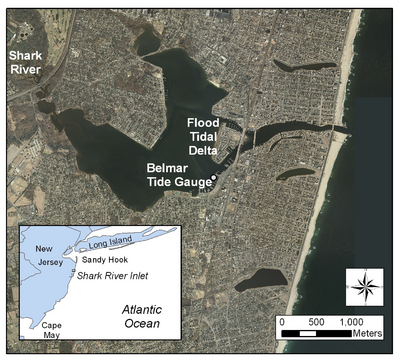
The CMS setup for Shark River Inlet provides is a succinct example for illustrating a number of methods and SMS tools that can be applied to most engineering projects. The area is characterized by being heavily structured, with a jettied inlet (and a jetty spur), developed bay shoreline (seawalls and riprap), and densely spaced groins, some of which on the south (up-drift) side have been notched. The overall goal of this guided example is to allow the user to work with real datasets, many of which were provided by the U.S. Army Corps of Engineers, New York District (NAN). | |||
Goals for the exercise: | |||
Assemble a base modeling grid | |||
Set up specific features in the CMS | |||
Develop several alternative grids | |||
Compare calculated channel morphology change to measured channel morphology | |||
2. Importing Bathymetric Datasets and Aerial Photographs | |||
The original datasets put together for creating the Shark River Inlet grid are provided as a combined file that has already had the projection and datums modified. The original files include the bathymetry from a sampled (filtered) LIDAR dataset, a sampled multibeam survey of the north and south channels and back bay, Corps of Engineers channel surveys (NAN), and NOAA’s Coastal Relief Model (offshore bathymetry) . The final combined dataset includes all of the above listed datasets, and the full channel bathymetry collected by the NAN in 1999. | |||
Revision as of 15:21, 14 May 2010

Topics:
- Introduction
- Importing Bathymetric Datasets and Aerial Photographs
- CMS-Flow Setup
- Grid Generation
- Bathymetry Preconditioning
- Auxiliary Datasets
- Boundary Conditions
- Model Parameters
- CMS-Wave Setup
- Grid Generation
- Model Parameters and Input Spectra
- Providing Sea Buoy Data to CMS-Wave
- Steering
- Viewing Results and Making Animation
- Calculation of Channel Infilling and Transport Rates
Normal 0 false false false MicrosoftInternetExplorer4 1. Introduction
The CMS setup for Shark River Inlet provides is a succinct example for illustrating a number of methods and SMS tools that can be applied to most engineering projects. The area is characterized by being heavily structured, with a jettied inlet (and a jetty spur), developed bay shoreline (seawalls and riprap), and densely spaced groins, some of which on the south (up-drift) side have been notched. The overall goal of this guided example is to allow the user to work with real datasets, many of which were provided by the U.S. Army Corps of Engineers, New York District (NAN).
Goals for the exercise:
Assemble a base modeling grid Set up specific features in the CMS Develop several alternative grids Compare calculated channel morphology change to measured channel morphology
2. Importing Bathymetric Datasets and Aerial Photographs
The original datasets put together for creating the Shark River Inlet grid are provided as a combined file that has already had the projection and datums modified. The original files include the bathymetry from a sampled (filtered) LIDAR dataset, a sampled multibeam survey of the north and south channels and back bay, Corps of Engineers channel surveys (NAN), and NOAA’s Coastal Relief Model (offshore bathymetry) . The final combined dataset includes all of the above listed datasets, and the full channel bathymetry collected by the NAN in 1999.