CPT: Difference between revisions
No edit summary |
No edit summary |
||
| Line 17: | Line 17: | ||
Setting the desired level of analysis is done through the CPT Home screen: https://itlgis01.usace.army.mil/CPTWeb/. Figure 1 shows the four levels of analysis provided by CPT; the desired level is chosen by simply clicking on the respective link. | Setting the desired level of analysis is done through the CPT Home screen: https://itlgis01.usace.army.mil/CPTWeb/. Figure 1 shows the four levels of analysis provided by CPT; the desired level is chosen by simply clicking on the respective link. | ||
[[ | [[Image:CPT_Home.jpg|400px|thumb|left|Fig. 1 – CPT Home screen]] | ||
| Line 25: | Line 25: | ||
The entities (reaches, Project, Districts, etc.) to be analyzed and or compared using CPT is determined via the selection made on the CPT Home screen. Once this selection is made, the user is taken to a Selection page wherein the desired entities can be selected from nested drop-down menus. Figure 2 shows the Selection page for Reach-level analysis. | The entities (reaches, Project, Districts, etc.) to be analyzed and or compared using CPT is determined via the selection made on the CPT Home screen. Once this selection is made, the user is taken to a Selection page wherein the desired entities can be selected from nested drop-down menus. Figure 2 shows the Selection page for Reach-level analysis. | ||
[[ | [[Image:CPT_Reach_Selection3.jpg|400px|thumb|right|Fig. 2 – CPT Reach Selection Screen]] | ||
| Line 33: | Line 33: | ||
Note that the entities available via the Selection screen will change depending on the level of analysis chosen on the CPT Home Screen. Figure 3 shows the Selection page when District-level analysis is specified by the user. In this case, no further drop-down menus become available after the Districts are selected, since the user has already reached the specified level of analysis. The format is the same for the Division and Project levels of analysis, respectively. | Note that the entities available via the Selection screen will change depending on the level of analysis chosen on the CPT Home Screen. Figure 3 shows the Selection page when District-level analysis is specified by the user. In this case, no further drop-down menus become available after the Districts are selected, since the user has already reached the specified level of analysis. The format is the same for the Division and Project levels of analysis, respectively. | ||
[[ | [[Image:CPT_District_Selection2.jpg|400px|thumb|left|Fig. 3 – CPT District Selection Page]] | ||
Revision as of 19:03, 28 July 2010
Channel Portfolio Tool (CPT)
POC: Dr. Kenneth Ned Mitchell
- Kenneth.n.mitchell@usace.army.mil
- 601-634-2022
- US Army Engineer Research and Development Center (ERDC)
- Coastal and Hydraulics Lab (CHL)
Active URL (Corps machines only): https://itlgis01.usace.army.mil/CPTWeb/
CPT is developmental software that is updated frequently.
1. CPT general layout
a. Setting the level of analysis (Reach, Project, District, Division)
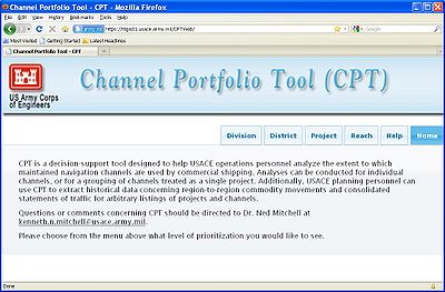
CPT is designed to enable analysis of commercial utilization of the Corps-maintained waterway infrastructure at a variety of coverage levels. At the most detailed level, individual channel sub-reaches may be chosen for analysis and compared to other sub-reaches in the USACE portfolio of navigation projects. However, in order to provide decision support to personnel at all levels of Corps management, CPT can also be used to analyze and compare commercial usage figures at the Project, District, and Division levels. For example, a District program manager might want to see which navigation project under his or her control handles the most exports of a particular commodity. CPT pulls from a large database that is maintained by the Corps’ Waterborne Commerce Statistics Center (WCSC). Setting the desired level of analysis is done through the CPT Home screen: https://itlgis01.usace.army.mil/CPTWeb/. Figure 1 shows the four levels of analysis provided by CPT; the desired level is chosen by simply clicking on the respective link.

- b. Selection of items to be ranked and/or analyzed
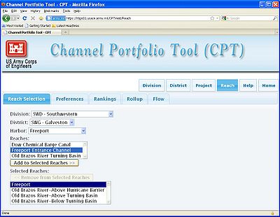
The entities (reaches, Project, Districts, etc.) to be analyzed and or compared using CPT is determined via the selection made on the CPT Home screen. Once this selection is made, the user is taken to a Selection page wherein the desired entities can be selected from nested drop-down menus. Figure 2 shows the Selection page for Reach-level analysis.

Starting at the Division level, the user chooses the appropriate selection from each successive drop-down menu. Reaches inadvertently selected may be removed at any time using the “Remove from Selected Reaches” button.
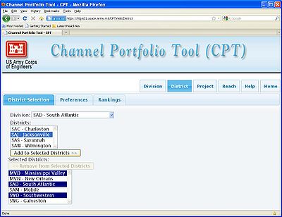
Note that the entities available via the Selection screen will change depending on the level of analysis chosen on the CPT Home Screen. Figure 3 shows the Selection page when District-level analysis is specified by the user. In this case, no further drop-down menus become available after the Districts are selected, since the user has already reached the specified level of analysis. The format is the same for the Division and Project levels of analysis, respectively.

- c. Explanation of Preferences
Once the user is done making selections using the drop-down menus, the Preferences tab immediately to the right of the Selection tab should be clicked in order to specify data filtering criteria and other query parameters. Figure 4 shows the Preferences page, and each of the user-specified query parameters is described in the following sections.
Fig. 4 – CPT Preferences Page showing Shoaling and Movement type specification
- i. Shoaling considerations
The latest version of CPT allows the user to specify a single, default shoaling rate to be applied uniformly across all selected sub-reaches. Subsequent versions of CPT will allow for upload of present channel controlling depths so that shoaling conditions are more accurately represented. In the meantime, the default shoaling feature allows the user to focus on the commercial shipping utilizing just the deepest portions of maintained channels, i.e. those depths most vulnerable to shoaling during a given budget cycle, and also those depths most dependent upon USACE maintenance dredging to remain clear for navigation. CPT indirectly calculates channel limiting depths for each year based on the deepest transiting vessel calls in the Waterborne Commerce database found to have utilized a given channel. The assumption made is that commercial shipping would utilize the deeper depths if they were in fact available. This assumption has significant limitations, and again, subsequent versions of CPT will allow for controlling depths to be entered directly by users throughout USACE to provide a more accurate representation of channel conditions. Figure 4 shows the Shoaling portion of the Preferences page, with 3 ft of shoaling specified by the user. Alternatively, the user may choose to ignore shoaling conditions altogether, in which case all tonnage (or $-value) transiting at all depths will be used as the scoring metric when ranking chosen entities.
- ii. Movement types to include
CPT provides the option of considering just particular traffic types (i.e. imports, exports, coastwise domestic, etc.) when comparing selections. These traffic types are listed in the Movements section of the Preferences page, as seen in Figure 4; the user has selected only imports and exports for consideration. Additional traffic types available include Domestic movements, representing shipments that travel over coastal and/or Great Lakes waters, and Internal movements, indicating shipments that remain on the inland river system. Intra-territory and Ferry traffic is not yet included within CPT but will be available in subsequent versions.
- iii. Docked vs. transiting tonnage
Within a given channel or project, waterborne commerce may load and unload at docks, piers, and berthing terminals, while other traffic may simply transit the channel without stopping while on its way to some other destination. In both instances, the channel in question supports those shipments in the course of their voyage, however the CPT user may wish to see one or the other for the purposed of their analysis. Figure 5 shows the portion of the CPT Preferences page found below the Movements section discussed above (and shown in Fig. 4).
Fig. 5 – CPT Preferences Page showing Tonnage Mode and Commodity specification
The two options presently available in CPT include “Transit” (selected in Fig. 5) and “Docked.” In this version of CPT, the “Transit” option actually considers both tonnage that docks within a reach and also through tonnage that transits without stopping. The “Docked” option counts just the tonnage that actually docks within a given reach. Subsequent versions of CPT will include a third toggle that isolates through tonnage from docked tonnage.
- iv. Commodity selection
The Waterborne Commerce database classifies cargo into 662 separate commodity listings. CPT allows the user to choose any subset of these codes for inclusion in the analysis. Figure 5 shows the Commodities section in the Preferences page, below the Tonnage Mode section discussed previously. The user may simply choose to include all commodities (as indicated in Fig. 5), or select individual commodity listings from the menu. Subsequent versions of CPT will feature nested commodity groupings and selections to make this process easier.
- v. Years of coverage
CPT presently offers coverage of waterborne commerce movements starting in 2003 up until 2007. Figure 6 shows the section of the Preferences page below the Commodities section wherein years of coverage are specified. The box indicating All Years of available data is checked as the default setting.
Fig. 6 – CPT Preferences showing Years and KML Settings sections
It should be noted that prior to 2005, draft information was not recorded for foreign vessels, therefore draft-profile charts cannot be generated using foreign cargo data from years 2003 and 2004.
- vi. Google Earth .kml settings
CPT allows for exporting of .kml files for viewing in Google Earth to help convey the relative significance of sub-reaches and deep-water waterway network links in terms of the tons and/or $-value of cargo utilizing those entities. Results from both Rankings queries and Flow queries can be exported for viewing in Google Earth.
Two methods are available for displaying CPT reaches and network links within Google Earth: 1) the “Polygon” option allows the user to define an upper and lower bound for the width of the overlays, and 2) the “Line” option uses simple lines between 1 and 10 pixels wide to represent channels and network links. Due to the way in which each option is rendered within the Google Earth viewing environment, it is recommended that the Polygon option be selected when comparing reaches within a single Project-sized area (e.g. Baltimore Harbor or the Galveston Bay area), while the Line option works better when wanting to see regional comparisons of channel significance (i.e. commodity flows along the East coast or a comparison of reaches in multiple harbors).
Figure 6 shows the KML Settings section of the Preferences page. In the example shown, the Polygon option is selected, with a minimum width of 528 ft and a maximum width of 5280 ft. Note that if the Line option were selected, the width values would need to be specified in terms of screen pixels, with a minimum and maximum of 1 and 10 pixels, respectively.
The Log/Linear toggle shown in Figure 6 determines the manner in which the width of each reach is scaled for display. Recall that the width of each reach overlay is determined by the tons or $-value utilizing the respective reach. The simplest way to convey this is to have a linear scale, with the highest-tonnage reach having the maximum specified width, and all subsequent reach widths scaled accordingly down to the reach with the fewest tons or $-value. However, often times the tonnage or $-value utilizing the selected reaches will vary by orders of magnitude, so the linear scaling can result in a less-than-ideal visual conveyance of the relative significance of each reach. To address this issue, CPT provides a Log scaling option, which uses a more gradual reduction in line width as the underlying tonnage or $-value decreases. Figure 7 gives a general idea of the differences between Linear and Log width scaling.
Fig. 7 – Linear and Log width scaling options for CPT Google Earth overlays
Figures 8 and 9 show the Polygon and Line overlay options, respectively. In each case, the clicking on the reach overlays shows the underlying tons and $-value.
Fig. 8 – Baltimore Harbor as shown using the CPT Google Earth polygon overlay option
Fig. 9 –Flow of traffic through the Perth Amboy Entrance Channel (New York Harbor) along US East Coast, as shown using the CPT Google Earth line overlay option
- vii. Saving Preferences
Once all filter criteria have been specified using the Preferences page, the Save Preferences button (Fig. 6, bottom of page) must be pressed before the query can be executed. Figure 10 shows the resulting screen, giving confirmation that the Preferences have been recorded and that the various analyses can now be performed.
Fig. 10 – CPT Preferences Saved! Message
- d. Viewing of Rankings, Roll-ups, and Flow tables
Once Preferences have been saved, the CPT user may select one of the three tabs shown to the left of the Preferences tab in Figure 10. The remainder of this users guide will give step-by-step instructions on how to use the Rankings, Rollup, and Flow features of CPT for analysis.