CMS-Flow Wave Forcing: Difference between revisions
No edit summary |
|||
| Line 1: | Line 1: | ||
__NOTOC__ | __NOTOC__ | ||
Steering is the coupling process between CMS-Flow and CMS-Wave. There are two types of coupling available (1) | |||
one-way coupling and (2) two-way coupling. In one-way coupling information is passed only in one direction whereas in two-way coupling information exchanged between both flow and waves. | |||
== User Specified Datasets == | Before coupling CMS-Wave and CMS-Flow, it is a good idea to test the CMS-Flow and CMS-Wave separately to make sure there are no problems with their grids, or input parameters. Once the CMS-Flow and CMS-Wave models have been setup properly and loaded in SMS, the steering can be initiated. | ||
== User Specified Datasets (One-way coupling) == | |||
[[Image:CMS-Flow_Model_Control_Wind-Wave.png|thumb|right|600px|SMS 10.1 | alt=SMS 10.1]] | [[Image:CMS-Flow_Model_Control_Wind-Wave.png|thumb|right|600px|SMS 10.1 | alt=SMS 10.1]] | ||
In this approach, precomputed wave height, period and direction datasets are provided to CMS-Flow. The advantage of this approach is that any wave model can be used and that the waves do not have to be recomputed for multiple CMS-Flow runs. The disadvantage is that the currents are not included in the wave model calculation (one-way coupling). The second approach is to run CMS-Flow and CMS-Wave together or in ''Steering'' mode. The user must provide several datasets of information which has been mapped to the flow grid geometery. | |||
# Radiation stress gradient | # Radiation stress gradient | ||
# Wave height | # Wave height | ||
| Line 13: | Line 16: | ||
'''CMS-Flow cards related to wave forcing (one-way coupling)''' | '''CMS-Flow cards related to wave forcing (one-way coupling)''' | ||
{| border= | {| border=1 | ||
! Card !! Arguments !! Type | ! Card !! Arguments !! Type | ||
|- | |- | ||
|WAVE_RSTRESS_DATASET || | |WAVE_RSTRESS_DATASET || File name Dataset path || character | ||
|- | |- | ||
|WAVE_HEIGHT_DATASET || | |WAVE_HEIGHT_DATASET || File name Dataset path || character | ||
|- | |- | ||
|WAVE_PERIOD_DATASET || | |WAVE_PERIOD_DATASET || File name Dataset path || character | ||
|- | |- | ||
|WAVE_DIRECTION_DATASET || | |WAVE_DIRECTION_DATASET || File name Dataset path || character | ||
|- | |- | ||
|WAVE_DISSIPATION_DATASET || | |WAVE_DISSIPATION_DATASET || File name Dataset path || character | ||
|} | |} | ||
== Steering Mode == | == Steering Mode (Two-way coupling) == | ||
In CMS-Flow versions v3.75 and older (explicit CMS-Flow), the steering was done by the SMS interface. The new inline CMS (implicit CMS-Flow) contains both CMS-Flow and CMS-Wave and performs the coupling process internally. Therefore, depending on what version of CMS-Flow wants to run, the steering process is slightly different. | |||
===CMS-Flow (V3.75 and older) and CMS-Wave=== | |||
Note that the input spectra need to be spaced at regular time intervals and begin at the same time as the CMS-Flow model. | |||
br style=clear:both / | |||
[[Image:Shark_Fig39.PNG|thumb|right|400px|Figure 39. Steering Module for the CMS.]] | |||
* Start Steering Module to run the CMS | |||
#. Be sure to save the flow and wave grids into the same folder, | |||
#. Open the SMS Steering Wizard by clicking on the menu ''Data'' nowiki|/nowiki ''Steering Module''. | |||
#. Click on ''CMS-Flow - CMS-Wave'', click next, and set as the following Figure'' ''30, click ''Start''. | |||
br style=clear:both / | |||
===CMS-Flow (V4.0 and newer) and CMS-Wave=== | |||
CMS Versions 4.0 and newer the steering process is done internally by the CMS. This means that that both CMS-Flow and CMS-Wave are contained within a single code or executable. Currently, this inline version of CMS only contains the implicit CMS-Flow. Therefore, if the user decides to switch from explicit to implicit solvers, the user must also change the CMS-Flow executable under the SMS preferences. To run the inline CMS in steering, the user must specify the steering options in the advanced cards and then execute the CMS-Flow from the SMS interface. | |||
br style=clear:both / | |||
[[Image:Shark_Fig40.PNG|thumb|right|400px|Figure 40. Changing the CMS-Flow model executable]] | |||
* Change the CMS-Flow executable to the inline code (see Figure 40). | |||
#. Click on ''Edit nowiki|/nowiki Preferences''. | |||
#. Under ''Model Executables'' change the name of the executable for CMS-Flow to the name of the executable provided in the DVD. The executable name should be something like CMS_2D_v4p0.exe. | |||
The next step is to provide the steering information using the advanced cards. Note that when running the inline CMS the couling between CMS-Flow and CMS-Wave is set to full. This means that both the water level and currents are passed from CMS-Flow to CMS-Wave and all of the wave information is passed from CMS-Wave to CMS-Flow. The information that needs to be provided is the steering interval, which is the time interval on which the CMS-Wave model is run and should also correspond with the time interval between input spectra. Note that the input spectra need to be spaced at regular time intervals and begin at the same time as the CMS-Flow model. The steering interval is provided in units of hours. | |||
br style=clear:both / | |||
[[Image:Shark_Fig41.PNG|thumb|right|400px|Figure 41. Setting the CMS steering information.]] | |||
* Set the steering information (See Figure 41) | |||
#. Click on ''CMS-Flow'' nowiki|/nowiki ''Model Control''… | |||
#. Enter the steering interval and CMS-Wave *.sim file using the cards shown in Figure 41. Note that the full path to the *.sim file must be provided within quotation marks. | |||
br style=clear:both / | |||
[[Image:Shark_Fig42.PNG|thumb|right|400px|Figure 42. Example of launching the inline CMS-Flow steering run.]] | |||
* Start Steering Module to run the CMS (see Figure 42) | |||
#. Load the CMS-Flow project | |||
#. Click on ''CMS-Flow'' nowiki|/nowiki Run CMS-Flow. | |||
#. When the model is finished, click on exit | |||
The inline code will produce two files named Intpcoef_flwav.bin, and Intpcoef_wavfl.bin. These files contain the interpolation information between the CMS-Flow and CMS-Wave grids. If the model is restarted the model will automatically detect these files and read them. | |||
br style=clear:both / | |||
---- | ---- | ||
[[CMS#Documentation Portal | Documentation Portal]] | [[CMS#Documentation Portal | Documentation Portal]] | ||
Revision as of 17:30, 23 August 2011
Steering is the coupling process between CMS-Flow and CMS-Wave. There are two types of coupling available (1)
one-way coupling and (2) two-way coupling. In one-way coupling information is passed only in one direction whereas in two-way coupling information exchanged between both flow and waves.
Before coupling CMS-Wave and CMS-Flow, it is a good idea to test the CMS-Flow and CMS-Wave separately to make sure there are no problems with their grids, or input parameters. Once the CMS-Flow and CMS-Wave models have been setup properly and loaded in SMS, the steering can be initiated.
User Specified Datasets (One-way coupling)
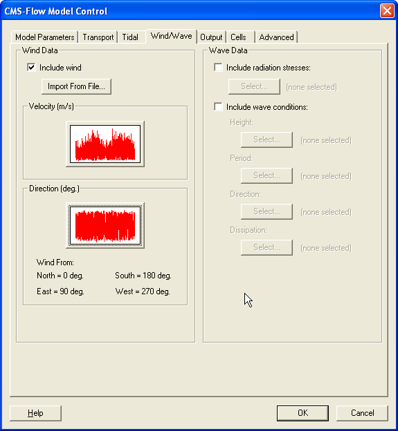
In this approach, precomputed wave height, period and direction datasets are provided to CMS-Flow. The advantage of this approach is that any wave model can be used and that the waves do not have to be recomputed for multiple CMS-Flow runs. The disadvantage is that the currents are not included in the wave model calculation (one-way coupling). The second approach is to run CMS-Flow and CMS-Wave together or in Steering mode. The user must provide several datasets of information which has been mapped to the flow grid geometery.
- Radiation stress gradient
- Wave height
- Wave period
- Wave direction
- Wave dissipation
CMS-Flow cards related to wave forcing (one-way coupling)
| Card | Arguments | Type |
|---|---|---|
| WAVE_RSTRESS_DATASET | File name Dataset path | character |
| WAVE_HEIGHT_DATASET | File name Dataset path | character |
| WAVE_PERIOD_DATASET | File name Dataset path | character |
| WAVE_DIRECTION_DATASET | File name Dataset path | character |
| WAVE_DISSIPATION_DATASET | File name Dataset path | character |
Steering Mode (Two-way coupling)
In CMS-Flow versions v3.75 and older (explicit CMS-Flow), the steering was done by the SMS interface. The new inline CMS (implicit CMS-Flow) contains both CMS-Flow and CMS-Wave and performs the coupling process internally. Therefore, depending on what version of CMS-Flow wants to run, the steering process is slightly different.
CMS-Flow (V3.75 and older) and CMS-Wave
Note that the input spectra need to be spaced at regular time intervals and begin at the same time as the CMS-Flow model.
br style=clear:both /
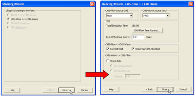
- Start Steering Module to run the CMS
- . Be sure to save the flow and wave grids into the same folder,
- . Open the SMS Steering Wizard by clicking on the menu Data nowiki|/nowiki Steering Module.
- . Click on CMS-Flow - CMS-Wave, click next, and set as the following Figure 30, click Start.
br style=clear:both /
CMS-Flow (V4.0 and newer) and CMS-Wave
CMS Versions 4.0 and newer the steering process is done internally by the CMS. This means that that both CMS-Flow and CMS-Wave are contained within a single code or executable. Currently, this inline version of CMS only contains the implicit CMS-Flow. Therefore, if the user decides to switch from explicit to implicit solvers, the user must also change the CMS-Flow executable under the SMS preferences. To run the inline CMS in steering, the user must specify the steering options in the advanced cards and then execute the CMS-Flow from the SMS interface.
br style=clear:both /
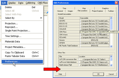
- Change the CMS-Flow executable to the inline code (see Figure 40).
- . Click on Edit nowiki|/nowiki Preferences.
- . Under Model Executables change the name of the executable for CMS-Flow to the name of the executable provided in the DVD. The executable name should be something like CMS_2D_v4p0.exe.
The next step is to provide the steering information using the advanced cards. Note that when running the inline CMS the couling between CMS-Flow and CMS-Wave is set to full. This means that both the water level and currents are passed from CMS-Flow to CMS-Wave and all of the wave information is passed from CMS-Wave to CMS-Flow. The information that needs to be provided is the steering interval, which is the time interval on which the CMS-Wave model is run and should also correspond with the time interval between input spectra. Note that the input spectra need to be spaced at regular time intervals and begin at the same time as the CMS-Flow model. The steering interval is provided in units of hours.
br style=clear:both /
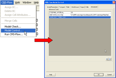
- Set the steering information (See Figure 41)
- . Click on CMS-Flow nowiki|/nowiki Model Control…
- . Enter the steering interval and CMS-Wave *.sim file using the cards shown in Figure 41. Note that the full path to the *.sim file must be provided within quotation marks.
br style=clear:both /
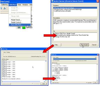
- Start Steering Module to run the CMS (see Figure 42)
- . Load the CMS-Flow project
- . Click on CMS-Flow nowiki|/nowiki Run CMS-Flow.
- . When the model is finished, click on exit
The inline code will produce two files named Intpcoef_flwav.bin, and Intpcoef_wavfl.bin. These files contain the interpolation information between the CMS-Flow and CMS-Wave grids. If the model is restarted the model will automatically detect these files and read them.
br style=clear:both /