GenCade Input Files: Difference between revisions
mNo edit summary |
mNo edit summary |
||
| Line 35: | Line 35: | ||
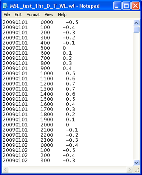
When time-dependent wave transmission is selected for a detached breakwater, it is necessary to include the water level information. This information is stored in the *.wl (water level) file. This file has three columns: the date (in YYYYMMDD), the time (between 0 and 2300 hours), and the water level. | When time-dependent wave transmission is selected for a detached breakwater, it is necessary to include the water level information. This information is stored in the *.wl (water level) file. This file has three columns: the date (in YYYYMMDD), the time (between 0 and 2300 hours), and the water level. | ||
[[Image:water_level_file.png|500px|thumb|left|Figure | [[Image:water_level_file.png|500px|thumb|left|Figure 6. Example *.wl]] | ||
<br style="clear:both" /> | |||
= Secondary parameter file (*.cntmcxsh) = | |||
If the user will be enabling Cross Shore or Monte Carlo capabilities, an additional parameter file will be written and must be present for GenCade (version 2.0 or later) to read. An example of this file is shown in the image below. | |||
[[Image:cntmcxsh_file.png|500px|thumb|left|Figure 7. Example *.cntmcxsh]] | |||
<br style="clear:both" /> | <br style="clear:both" /> | ||
Return to [[GenCade|GenCade Main Page.]] | Return to [[GenCade|GenCade Main Page.]] | ||
Revision as of 22:49, 18 January 2024
After saving the GenCade project, several files will be created in the user specified folder. These files include *.gen, *.shi, *.shr, *.wave, *.shdx, and *.wl. For example, if the name of the project is test, the input files would be named test.gen, test.shi, test.shr, and test_wave1.wave. In order to run GenCade, at least the *.gen, *.wave, and *.shi files are needed. The *.shr file is necessary for a case with a regional contour, while *.shdx is created when variable grid resolution occurs. The *.wl file is only created when using time-dependent wave transmission for a detached breakwater.
GenCade Control file (*.gen)
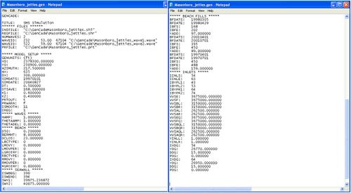
The *.gen file is the control file. The first section of this file lists information about the other input and output files. The first line under files shows the path for the location of the initial shoreline. If the case has a regional contour, the next line will list the location for the regional contour. The next line specifies the number of wave gages included for the simulation while the next lines list the cell of the wave gage, the depth, number of time steps for the wave information, and the path for each wave gage. The next section of the *.gen file is the model setup. This section includes the grid origin and orientation, the simulation start and end date, the time step, the longshore sand transport coefficients (K1 and K2), and the number of cells in the offshore contour smoothing window (ISMOOTH). The next section of the *.gen file is the waves section. This section includes the height amplification factor, angle amplification factor, and angle offset. The D50, berm height, closure depth, and boundary conditions are found under the beach heading. Seawalls, beach fills, inlets, groins, and other features included in the conceptual model follow the beach section in the *.gen file.
Initial Shoreline file (*.shi)
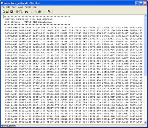
The *.shi file is the initial shoreline data file. Each number in this file represents a cell, and the number is the distance the shoreline is offset for the baseline.
Regional Contour file (*.shr)
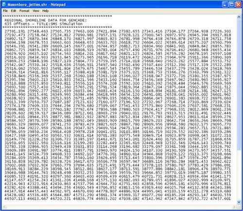
The regional contour information is included in the *.shr file. If the case does not need a regional contour, this file will not be created. This file has the same format as the *.shi file. Each number represents the distance the regional contour is offset from the baseline.
Wave files (*.wave)
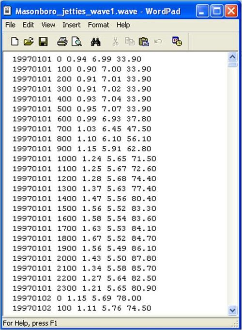
All of the wave information will be included in the *.wave files. There will be one *.wave file for each wave gage. The wave gage assigned to the lowest cell number will be the represented in the first *.wave file. For example, if the first wave gage is assigned to cell 10 and the second is assigned to cell 100, the first wave gage will be *wave1.wave and the wave gage assigned to cell 100 will be *wave2.wave. The wave information in the file is identical to what the user copied into the SMS.
Variable grid resolution file (*.shdx)
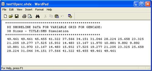
In cases where variable grid resolution is used, an additional file called *.shdx will be created. Each number in the file represents the distance of each cell in the grid. If the user would like to make a plot outside of the SMS, this file is necessary to determine the distance along the shore.
Water level file (*.wl)
When time-dependent wave transmission is selected for a detached breakwater, it is necessary to include the water level information. This information is stored in the *.wl (water level) file. This file has three columns: the date (in YYYYMMDD), the time (between 0 and 2300 hours), and the water level.
Secondary parameter file (*.cntmcxsh)
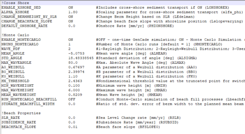
If the user will be enabling Cross Shore or Monte Carlo capabilities, an additional parameter file will be written and must be present for GenCade (version 2.0 or later) to read. An example of this file is shown in the image below.
Return to GenCade Main Page.