JALBTCX/PFEStep1: Difference between revisions
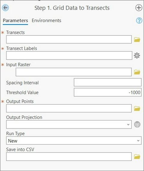
Created page with "{{DISPLAYTITLE:Profile Feature Extraction: Step 1 - Grid Data to Transects}} alt=A screenshot of the first step of the Profile Feature Extraction Toolbox, grid data to transects. All inputs are blank and are mentioned below in the report. |thumb|573x573px|Figure 5. Step 1: Grid Data to Transects Geoprocessing Pane. Red asterisks indicate required values. '''Summary:''' This step generates points along the length of each transect starting at the base..." |
mNo edit summary |
||
| Line 30: | Line 30: | ||
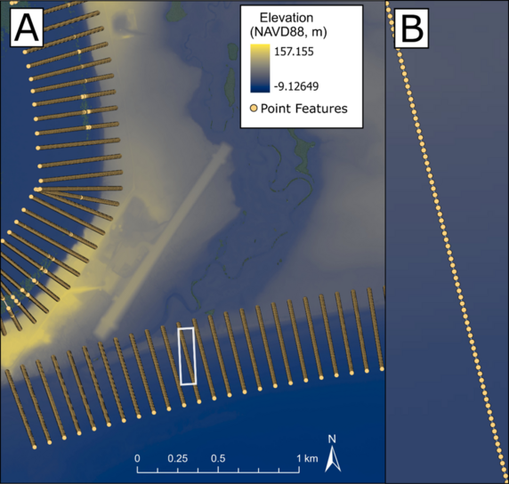
[[File:PFEStep1 Example.png|alt=A GIS set of screenshots showing points along transects. Figure A displays the transects at a large scale, while B displays an individual transect so individual points along that transect can be seen clearly. |none|thumb|572x572px|Figure 6. Example Point Feature output for Golovin, AK. The inset map (B) shows the individual extracted points at one meter spacing along the transect highlighted in (A).]] | [[File:PFEStep1 Example.png|alt=A GIS set of screenshots showing points along transects. Figure A displays the transects at a large scale, while B displays an individual transect so individual points along that transect can be seen clearly. |none|thumb|572x572px|Figure 6. Example Point Feature output for Golovin, AK. The inset map (B) shows the individual extracted points at one meter spacing along the transect highlighted in (A).]] | ||
==Useful Links== | |||
[[JALBTCX|JALBTCX Main Documentation Page]] | |||
[[JALBTCX/PFEReferences|References: Profile Feature Extraction]] | |||
Revision as of 15:38, 26 September 2024

Summary: This step generates points along the length of each transect starting at the baseline. Each point will contain information needed to create profiles, including point elevation extracted from the corresponding DEM, transect numbers and distance from each point to the baseline. Point spacing is equal to the DEM resolution unless it is user defined.
Transects: The transects generated previously that extend from the baseline to the depth of closure. This step honors selection of the transects in the case that only certain transects need points generated.
Transect Labels: A dropdown menu to select the numbering field from the transect attribute table that provides each of the transects with a unique value (e.g., StTransNum).
Input Raster: The DEM(s) that elevations will be extracted from along each transect. The DEM(s) specified should represent a single survey (see best practices).
Spacing Interval: The horizontal distance between output points along the transects. If blank, this will be set to the cell size of the input DEM(s). If specified, the unit is the horizontal unit of the input DEM(s).
Threshold Value: The elevation value that specifies false DEM coverage (e.g. a hydroflattened value). All values equal to or less than this elevation will be set to null and thus not be extracted.
Output Points: The full file path, including name and file extension, of the output points file. The file extension can either be a feature class (if in a .gdb) or a shapefile (if in a file folder).
Output Projection: Desired projection of the output points. If left blank, projection of output points will be the same as the input transects.
Run Type: The specification of either a “New” or “Continued” run. “Continued” runs are leveraged if this tool previously failed on a “New” run and the user prefers the toolbox should pick up where it left off instead of starting over.
Save to CSV: The full file path, including name and file extension, of a .csv copy of the output points including transect label, range from baseline, coordinates (x/y or lat/lon), and elevation.
Best Practices & Example Data:
1. The input DEM(s) should represent a single survey as only one set of output points is generated each time the tool is run. If multiple datasets are being leveraged, the tool should be run multiple times, specifying new input DEM(s) each time the tool is run.
2. Keeping the same projection for baselines, transects, input DEM(s), points, and extracted features is preferred to reduce unit conversion errors.
The data seen in Figure 6 below are from the Golovin, AK dataset and displays output point data from Step 1 that are spaced at the native 1 meter resolution of the input DEM. Point data are only created along transects where elevation data coverage exists.
