Field Experiment Wave Validation Case 2: Difference between revisions
| Line 6: | Line 6: | ||
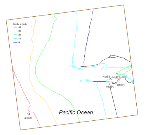
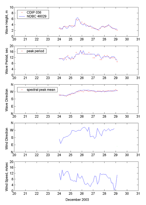
CMS-Wave simulations were conducted on a model grid of 440 600 cells, with cell size of 30 m 30 m (Figure 1). Directional wave spectra from CDIP 036 served as the input, discretized in 30 frequency bins (0.04 to 0.33 Hz with 0.01-Hz increment) and 35 direction bins (5 deg spacing of a half-plane), at the seaward boundary. Five days of wave data over 24 28 December 2003 were analyzed for comparison to the calculation (Osborne and Davies 2004). A winter storm occurred during this 5-day interval with the largest offshore measured wave height exceeding 6 m. CMS-Wave was run in steering at 3-hr interval with the CMS-Flow to account for the influence of waves with current and tides. A diffraction intensity value of 2 and a forward reflection coefficient of 0.3 were specified. A constant bottom friction coefficient (''c''<sub>''f''</sub>) of 0.005 was specified in the model. Figure 2 shows the wave measurements at NDBC 46029 and CDIP 036 for 24-29 December 2003. | CMS-Wave simulations were conducted on a model grid of 440 600 cells, with cell size of 30 m 30 m (Figure 1). Directional wave spectra from CDIP 036 served as the input, discretized in 30 frequency bins (0.04 to 0.33 Hz with 0.01-Hz increment) and 35 direction bins (5 deg spacing of a half-plane), at the seaward boundary. Five days of wave data over 24 28 December 2003 were analyzed for comparison to the calculation (Osborne and Davies 2004). A winter storm occurred during this 5-day interval with the largest offshore measured wave height exceeding 6 m. CMS-Wave was run in steering at 3-hr interval with the CMS-Flow to account for the influence of waves with current and tides. A diffraction intensity value of 2 and a forward reflection coefficient of 0.3 were specified. A constant bottom friction coefficient (''c''<sub>''f''</sub>) of 0.005 was specified in the model. Figure 2 shows the wave measurements at NDBC 46029 and CDIP 036 for 24-29 December 2003. | ||
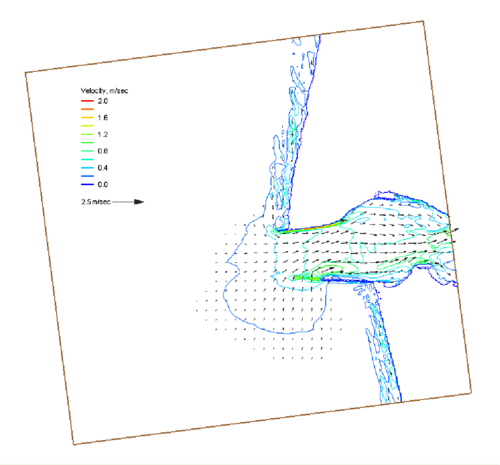
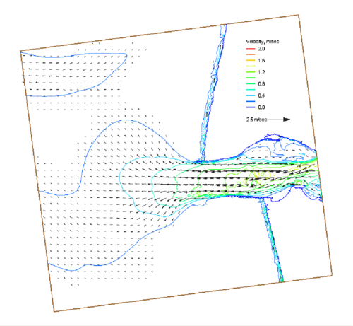
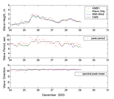
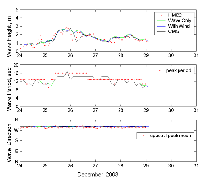
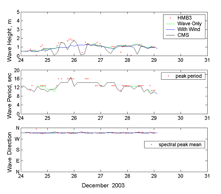
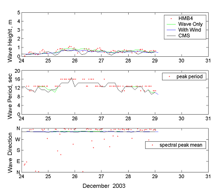
CMS-Wave was run to examine three different conditions: (1) wave transformation only, (2) wave transformation including local wind input, and (3) coupling with CMS-Flow (with wind, tide, and wave-current interaction). Figures 3 and 4 show calculated maximum current fields during the peak flood and ebb cycles, respectively, in the 5-day wave simulation coupled with the CMS-Flow. Figures | CMS-Wave was run to examine three different conditions: (1) wave transformation only, (2) wave transformation including local wind input, and (3) coupling with CMS-Flow (with wind, tide, and wave-current interaction). Figures 3 and 4 show calculated maximum current fields during the peak flood and ebb cycles, respectively, in the 5-day wave simulation coupled with the CMS-Flow. Figures 5 to 8 compare calculated results to the measurements. Because the offshore wave likely has reached the fully developed sea under the mild wind condition in the simulation, the influence of wind input on the wave field is insignificant. The effect of shallower water to waves is evident in the comparison of calculated results with data at sta HMB3 and HMB4. The effect of current is more evidenced at sta HMB1 and HMB2, which are located in relatively deep water and closer to the navigation channel. Calculated wave results are overall more satisfactory from the numerical simulation coupled with the CMS-Flow. | ||
'''Table 1. Coordinates of wave monitoring stations at Grays Harbor. ''' | '''Table 1. Coordinates of wave monitoring stations at Grays Harbor. ''' | ||
Latest revision as of 16:25, 23 November 2010
Grays Harbor Entrance
Grays Harbor, located on the coast of southwest Washington, is one of the largest estuaries in the continental United States. Spring tidal prism reaches 570 million m3, corresponding to the surface area of 200 km2 at mean tide level and a tidal range of 2.8 m. The entrance is approximately 2 km wide, and a deep-draft navigation channel is maintained at 12-13 m relative to mean lower low water. The entrance is protected by two rubble-mound jetties. The entrance to Grays Harbor experiences extreme Northwest Pacific waves during winter. Significant wave heights commonly exceed 6 m in winter storms. Strong ebb currents that exist between the jetties can increase wave height by as much as 0.5 to 1.5 m as observed in the inlet entrance.
Strong wave refraction and diffraction at the eastern end of the south jetty contribute to increased beach erosion in Half Moon Bay. To examine the influence of waves and currents in Half Moon Bay, wave and current data were collected at four stations between December 2003 and February 2004. Table 1 presents the location of four measurement stations (Osborne and Davies 2004). During the same time intervals, offshore wave information is available from a Coastal Data Information Program (CDIP) Buoy 036 (46°51.39'N, 124°14.67'W) in water of 40 m (mtl) and from National Data Buoy Center (NDBC) Buoy 46029 (46°8.63'N, 124°30.7'W), located approximately 100 km south-southeast of Grays Harbor. Ocean surface wind measurements are also available from Buoy 46029. Figure 83 shows the location map and local data-collection stations (Buoy 46029 and Half Moon Bay stations HMB1 to HMB4).
CMS-Wave simulations were conducted on a model grid of 440 600 cells, with cell size of 30 m 30 m (Figure 1). Directional wave spectra from CDIP 036 served as the input, discretized in 30 frequency bins (0.04 to 0.33 Hz with 0.01-Hz increment) and 35 direction bins (5 deg spacing of a half-plane), at the seaward boundary. Five days of wave data over 24 28 December 2003 were analyzed for comparison to the calculation (Osborne and Davies 2004). A winter storm occurred during this 5-day interval with the largest offshore measured wave height exceeding 6 m. CMS-Wave was run in steering at 3-hr interval with the CMS-Flow to account for the influence of waves with current and tides. A diffraction intensity value of 2 and a forward reflection coefficient of 0.3 were specified. A constant bottom friction coefficient (cf) of 0.005 was specified in the model. Figure 2 shows the wave measurements at NDBC 46029 and CDIP 036 for 24-29 December 2003.
CMS-Wave was run to examine three different conditions: (1) wave transformation only, (2) wave transformation including local wind input, and (3) coupling with CMS-Flow (with wind, tide, and wave-current interaction). Figures 3 and 4 show calculated maximum current fields during the peak flood and ebb cycles, respectively, in the 5-day wave simulation coupled with the CMS-Flow. Figures 5 to 8 compare calculated results to the measurements. Because the offshore wave likely has reached the fully developed sea under the mild wind condition in the simulation, the influence of wind input on the wave field is insignificant. The effect of shallower water to waves is evident in the comparison of calculated results with data at sta HMB3 and HMB4. The effect of current is more evidenced at sta HMB1 and HMB2, which are located in relatively deep water and closer to the navigation channel. Calculated wave results are overall more satisfactory from the numerical simulation coupled with the CMS-Flow.
Table 1. Coordinates of wave monitoring stations at Grays Harbor.
| Station | Coordinates | Depth, mtl (m) |
| HMB1 | 46o54'36"N, 124o07'30"W | 8.0 |
| HMB2 | 46o54'29"N, 124o06'50"W | 4.0 |
| HMB3 | 46o54'15"N, 124o07'04"W | 1.8 |
| HMB4 | 46o54'15"N, 124o07'18"W | 2.2 |
