CMS-Flow Rubble Mound Structures (DRAFT)
Introduction
Rubble mounds are commonly utilized in the construction of breakwaters, jetties, revetments, and groins. These structures play an essential role in harbor protection, channel navigation, shoreline defense, and in managing flow, sediment movement, and wave energy mitigation. Figure 1 illustrates the implementation of a rubble mound breakwater. Given their significant impact on hydrodynamic behavior and sediment dynamics in coastal areas, it is critical for the CMS to accurately simulate the influence of rubble mound structures.
Usage of Rubble Mounds for CMS in the SMS
Early SMS versions (< 13.0)
Previous documentation (Link given below) described the formulation and implementation of Rubble Mound structures in CMS, detailing input requirements for SMS versions up to 11.2. This implementation required hand-manipulation of the CMS-Flow parameter files to add in lists of cells and option values.
A technical note was started in 2024 for the newer implementation of Rubble Mounds. With the implementation of the other structures being imminent in SMS 13.4, the material for Rubble Mounds will be incorporated into a larger Special Report in FY25 that covers all four structures. The original method for implementing Rubble Mounds in CMS is covered by the technical note listed below.
Later SMS versions (13.0 to 13.3.8)

An undocumented update in SMS version 13.0 introduced a method to use constant values for cells enclosed within a polygon. There was no implementation of datasets to hold the parameter values in this version, however. This implementation created a "Rubble Mound Jetties" coverage that the user must populate and attach to the CMS-Flow simulations.
Recent SMS version (13.3.9+)
The rubble mound polygon dialog in SMS 13.3.9 and later was modified to allow for user-selection of either constant values or datasets for rock diameter, base depth, and porosity.
Future SMS versions (13.4.x)

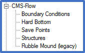
- The existing "Rubble Mound Jetties" coverage beneath the CMS-Flow model option in SMS 13.3 and earlier has been renamed "Rubble Mound (legacy)" in the new interface.
- A new "Structures" coverage has been added beneath the CMS-Flow model option in SMS 13.4 and later. This one coverage will handle Rubble Mound structures as well as three new types: Culverts, Weirs, and Tide Gates.
- In the new coverage, Rubble Mound structures will continue to be defined with polygons where each can have a set of attributes (either constant or from a dataset).
- The "Structures" coverage will need to be applied to the CMS Simulation in order to export the appropriate cards to the parameter file.
Values needed by the CMS for each Rubble Mound polygon are listed in the table below. If there is a user-definable option in the dialog for the user to enter a value, the word 'Dialog' is shown in column 3, otherwise the words 'No dialog' are written in column 2.
| Cell IDs | No dialog | |
| Name | User-entry | Dialog |
| Rock Diameter | Dataset or Constant | Dialog |
| Porosity | Dataset or Constant | Dialog |
| Base Depth | Dataset or Constant | Dialog |
| Computation method | Choice of three options | Dialog |
SMS will handle the assignment of the appropriate values for Cell IDs.
CMS-Flow specific information
The parameters/selections for each Culvert feature arc will be exported to the ‘.cmcards’ file in the form of a block of values. This implementation has been confirmed to work with CMS 5.3.12 and later.
- The Culvert parameter cards needed for each culvert are added to a structure block with a corresponding BEGIN/END statement for each culvert are listed in the table below.
- Most cards take one parameter, others take two. This is defined in column 3.
- Cards that are dependent on other choices are indicated in column 5.
- In cases where multiple values are to be written for a card, the value corresponding to the Bayside should be written first followed by the Seaside value.
- For readability and to be consistent with other cards in the .cmcards file, all values should start in column 36 and 3 spaces written between each value per line if more than one.
| Cardname | Indent 2
spaces? |
Number
of vals |
Type of value
written |
Dependent on | Notes |
|---|---|---|---|---|---|
| CULVERT_V2_BEGIN | NO | 0 | N/A | ||
| CELLS | YES | 2 | <int> <int> | Bay, then Sea | |
| TYPE | YES | 1 | ‘CIRCLE’ or ‘BOX’ | ||
| FLAP_GATE | YES | 1 | ‘ON’ or ‘OFF’ | ||
| RADIUS | YES | 1 | <real> | TYPE == ‘CIRCLE’ | |
| WIDTH | YES | 1 | <real> | TYPE == ‘BOX’ | |
| HEIGHT | YES | 1 | <real> | TYPE == ‘BOX’ | |
| LENGTH | YES | 1 | <real> | ||
| DARCY_FRICTION_FACTOR | YES | 1 | <real> | ||
| MANNINGS_COEFFICIENT | YES | 1 | <real> | ||
| INVERT_ELEVATIONS | YES | 2 | <real> <real> | Bay, then Sea | |
| ENTRY_HEAD_LOSS_BAY | YES | 1 | <real> | ||
| ENTRY_HEAD_LOSS_SEA | YES | 1 | <real> | ||
| EXIT_HEAD_LOSS_BAY | YES | 1 | <real> | ||
| EXIT_HEAD_LOSS_SEA | YES | 1 | <real> | ||
| OUTFLOW_ANGLES | YES | 2 | <real> <real> | Bay, then Sea | |
| CULVERT_V2_END | NO | 0 | N/A |
An example culvert block is shown below:
CULVERT_V2_BEGIN
  CELLS                             14334   14348
  TYPE                              CIRCLE
  FLAP_GATE                         OFF
  RADIUS                            0.9
  LENGTH                            30.3
  DARCY_FRICTION_FACTOR             0.04
  MANNINGS_COEFFICIENT              0.03
  INVERT_ELEVATIONS                 -1   -1
  ENTRY_HEAD_LOSS_BAY               0.4   0.4
  ENTRY_HEAD_LOSS_SEA               0.4   0.4
  EXIT_HEAD_LOSS_BAY                0.6   0.6
  EXIT_HEAD_LOSS_SEA                0.6   0.6
  OUTFLOW_ANGLES                    180.0   0.0
CULVERT_V2_END
Last update 9/25/2024
Back to CMS-Flow Structures page
Back to Documentation Portal
Last update 9/24/2024
Back to CMS-Flow Structures page
Back to Documentation Portal