Lab Wave Validation Case 2
Case 2: Waves breaking on plane beach
Visser (1991) conducted eight laboratory experiments, labeled as Exp. 1 to Exp. 8, with monochromatic incident waves that broke on a planar beach and generated a longshore current. A large data set of wave, current, and water level was collected for a number of incident wave conditions tested for two beach slopes (1:10 and 1:20) and two different bottom roughnesses. In this report, Visser Exps. 4 to 7 were selected for model validation because these have the same bottom composite slopes and the most complete measurements. The beach had a 1:10 slope for the first seaward 1-m distance, 1:20 slope for the next 5-m distance, and a flat bottom for the next 5.9 m to the wave generator. Exps. 4 through 6 were performed on a concrete bed, where the bottom friction is expected to be small and, therefore, neglected in the wave numerical simulation. For Exp. 7, the 1:20 slope bottom was roughened by a thin layer (0.5-1.0 cm) of gravel grouted on the concrete floor. Table 1 presents the incident wave conditions.
Table 1. Incident wave conditions.
| Exp. | Hs '(cm)'a | Tp '(sec)'a | fp '(Hz)'b | ' '(deg)c |
| 4 | 7.8 | 1.02 | 0.98 | 15.4 |
| 5 | 7.1 | 1.85 | 0.54 | 15.4 |
| 6 | 6.9 | 0.70 | 1.43 | 15.4 |
| 7 | 7.8 | 1.02 | 0.98 | 15.4 |
| a. Monochromatic wave. b. fp=1/Tp. c. Wave direction relative to shore-normal. | ||||
CMS-Wave was run at the laboratory scale. The model grid consisted of 90 cross-shore and 243 alongshore square cells, each 10 cm × 10 cm, to cover the entire basin in these experiments. The spectral transformation was computed in CMS-Wave on 11 frequency bins (covering the range of +/ 0.05 Hz of the incident monochromatic wave frequency at 0.01-Hz increment) and 35 direction bins (covering a half-plane with 5-deg spacing). The incident monochromatic, unidirectional wave spectrum was specified in a single frequency and direction bin at the seaward boundary. The input current and water level fields were interpolated across shore and averaged alongshore from the data. For Exp. 7 with the gravel floor, a constant bottom friction coefficient cf of 0.01 was specified in CMS-Wave and was found to produce good wave estimates.
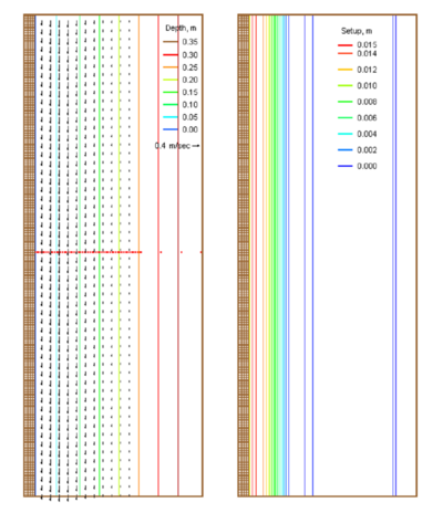
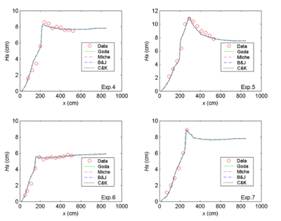
Figure 1 shows an example of input current and water level fields to CMS-Wave for the Exp. 4. Figure 2 compares the measured and calculated across shore wave heights for Exp. 4 through 7. The calculated wave height agrees well with the measurements for four different depth-limiting breaking formulas implemented in CMS-Wave.

