CMS-Flow Numerical Methods: Sediment Transport
Sediment Transport Transport Equations
The sediment transport equations are discretized using the methods described in Numerical Methods: General Transport Equation and are not repeated here.
Bed Material Sorting
The bed material sorting equation
| (2) |
is discretized as
| (3) |
where is the change in the top elevation of the second bed layer and The mixing layer or active layer thickness calculation is slightly modified to avoid excessively small layers as
| (4) |
where is the bed form height, and are the user-specified minimum and maximum mixing layer thicknesses, respectively.
The thickness of the second layer is calculated as The bed material gradation in the second layer is calculated from the following discretized form
| (5) |
| (6) |
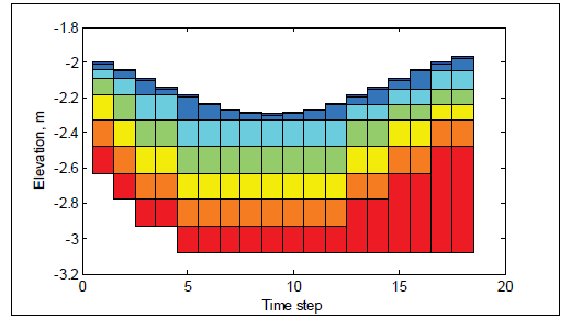
In order to avoid sediment layers from becoming extremely thin or thick, a layer merging and splitting algorithm is implemented between layers 2 and 3. Here, the subscript 2 corresponds to the second layer. To illustrate the bed layering process, Figure 1 shows an example of the temporal evolution of seven bed layers during erosional and depositional regimes.
It is noted that in order to maintain a constant number of bed layers, the bottom two layers are merged if the second layer is split or a new layer is created at the bottom using the bed composition and thickness of the bottom layer.

Figure 1. Schematic showing an example bed layer evolution. Colors indicate layer number and not bed composition.
Avalanching
When the slope of a non-cohesive bed,(), is larger than the angle of repose, (), the bed material will slide (avalanche) to form a new slope approximately equal to the angle of repose. The process of avalanching is simulated by enforcing while maintaining mass continuity between adjacent cells. The following equation for bed change due to ava-lanching is obtained by combining the equation for angle of repose and the continuity equation between two adjacent cells:
| (7) |
where is the cell center distance between cells P and N , is the cell area, is an under-relaxation factor (approximately 0.25-0.5), and H(X) is the Heaviside step-function representing the activation of avalanching and equal to 1 for . The sign function, (sgn X) , is equal to 1 for and accounts for the fact that the bed slope may have a negative or positive sign. Equation 7 is applied by sweeping through all computational cells to calculate and then modifying the bathymetry as . Because avalanching between two cells may induce additional avalanching at neighboring cells, the above sweeping process is repeated until avalanching no longer occurs. The under-relaxation factor, (), is used to stabilize the avalanching pro-cess and to avoid overshooting since the equation is derived considering only two adjacent cells but is summed over all (avalanching) neighboring cells. Equation (7) above may be applied to any grid geometry type (i.e. triangles, rectangles, etc.) and for situations in which neighboring cells are joined at corners without sharing a cell face.
Hard bottom
The sediment transport and bed change equations assume a loose bottom in which the bed material is available for entrainment. However, hard bottoms may be encountered in practical engineering applications where bed materials are non-erodible, such as bare rocks, carbonate reefs, and concrete coastal structures. Hard-bottom cells in CMS are handled by modifying the equilibrium concentration as in both the sedment transport and bed change equations. The bed-slope term in the bed change equation is also modified so that only deposition (no erosion) may occur at hard-bottom cells.
Implicit Semi-Coupling Procedure
For a semi-coupled sediment transport model, the sediment calculations are decoupled from the hydrodynamics but the sediment transport, bed change, and bed material sorting equations are coupled at the time-step level and thus solved simultaneously. A modified form of the iteration procedure of Wu (2004) is implemented in CMS. The equations are ob-tained by substituting into the bed change and sorting equations and then substituting the sorting equation into the bed change equation.
Summary of Sediment Transport Semi-Coupling Procedure:
- 1. Calculate bed roughness and bed shear stresses
- 2. Calculate the mixing layer thickness
- 3. Calculate the potential sediment concentration capacity
- 4. Guess the new bed composition as
- 5. Calculate the fractional concentration capacity
- 6. Solve transport equations for each sediment size class for
- 7. Calculate the total and fractional bed changes
- 8. Determine the bed sorting in the mixing layer;Repeat Step 5 and iterate until convergence.
- 9. Update the bed elevation as
- 10. Calculate the bed gradation in the bed layers below the mixing layer
- 11. Calculate avalanching.
- 12. Correct the sediment concentration due to flow depth change.
When using the explicit time-stepping scheme, the sediment transport and morphology change are solved at a time-step which may be equal to or multiples of the hydrodynamic time-step for efficiency. However, when using the implicit time-stepping scheme, the time-step is relatively big and on the order of 10 min. Because the time-step is so big, it is not necessary to use different time-steps for hydrodynamics and sediment transport. In addition, using the same time-step for hydrodynamics and sediment transport provides a better mass balance. For these reasons, the sediment transport time-step is always set to the hydrodynamic time-step in the implicit time-stepping scheme.