Weirs
Representation of Weirs in the Coastal Modeling System
By Christopher Reed and Alejandro Sánchez
Last Date Modified: September 17, 2010
Introduction
Weirs are a common coastal engineering structure used to control flow and can affect sediment transport. They are typically used in weir jetties or in wetlands to control discharges, provide flood control, act as salinity barriers and optimally distribute freshwater to manage salinity regimes and sedimentation rates and deposition patterns. Since these structures are a significant component of hydrodynamic and sediment transport controls in the coastal zone, it is important that the CMS simulate their effects. The simulation of weirs is based on the standard weir equation for either sharp-crested or broad-crested weirs, with a foundation in Bernoulli’s equation. The implementation of weirs in the CMS is validated in two applications on the lower Mississippi River. The weirs are applied in the simulation of flow over the Bonne Carrie spillway north of New Orleans.
Formulation
The Hydraulic Engineering Center (HEC, 2010) approach for calculating flow over rectangular weirs is adopted here. The form of the weir flow equation as presented in HEC (2010) is:
| (1) |
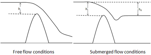
where is the flow rate over the weir crest, is the weir coefficient, is the weir crest length, is the upstream water depth above the crest, and is the submergence correction factor (also referred to as the drowned flow reduction factor). A definition schematic for both the free flow and submerged flow conditions is provided in Figure 1.

An inspection of Equation 1 reveals that the weir coefficient is dimensional. In CMS, the the equation is re-written as:
| (2) |
where is the acceleration due to gravity and . In this form, the coefficients are independent of the measurement system (i.e. Metric or English). The value for the weir coefficient depends on the upstream and downstream geometry of the weir. Ranges for the coefficient suggested in HEC (2010) are listed in Table 1.0.
Table 1.0. Suggested Weir Coefficient Values.
| Configuration | Range* |
| Sharp-crested | 0.55 – 0.58 |
| Broad-crested | 0.46– 0.55 |
* values in HEC (2010) converted to
Super-critical flow conditions occur when the flow is independent of the tail-water elevation. These conditions occur when the tail-water elevation is sufficiently low that the sub-critical coefficient is equal to 1.0. For submerged conditions a different approach is used for setting . For sharp-crested weirs, the coefficient is based on the equation by Villemonte (1947):
| (3) |
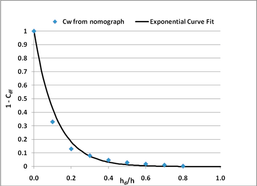
where and are defined in Figure 2. For broad-crested weirs, the value of is calculated by fitting a curve to data from USACE EM 1110-2-1603 (plate 3-5, Section A-A). An exponential curve was fit to the Section A-A data. The fit is shown in Figure 2 and the equation for is:
| (4) |

Numerical Implementation
The CMS-Flow explicit solver uses a staggered grid for the basis of the numerical solution. Weirs are implemented on the cell faces by specifying the two adjacent cells. The order of the cell specification is not critical for the weir implementation since the algorithm implemented in the CMS will determine the flow regime and the flow direction from the specified weir crest elevation and the water elevation in the adjacent cells. Figure 6 shows a typical CMS grid with a weir specified at a cell face.

In addition to the weir location,the user must also specify the crest elevation relative to the model datum, crest length L and the coefficient QUOTE . Multiple weirs can be specified at each face and the total flow across the face is the sum of the flow calculated for each individual weir. The momentum flux associated with the flow over the weir (and subsequently across the CMS cell face) is included in both the mass balance and the momentum balance calculations. Also, a weir can be specified as additive or replacing the cell face momentum flux that is calculated using the CMS solver. When the replacing weir type is specified, the flow from all weirs associated with the cell face replaces the calculated momentum flux. If an additive weir is specified, then the final momentum flux for the cell face is calculated as the weighted sum of the weir and momentum equations fluxes:
Where and are the momentum equations shallow water and weir equations, is the total flow across the face, and the fractions and for the momentum equation and weir flow contributions are defined as:
The application of the additive weir type would be applicable when a weir is set in a levee or other elevated structure. In cases where the levee is over topped the flow across the levee would be a combination of the weir flow and the flow over the levee surface.
The total flux across the cell face will be the sum of all weirs specified for that cell face. However, only the fluxes associated with the weirs will be included in the momentum balance.
When salinity or sediment transport is included in simulations with weirs, the salinity and suspended sediment will be transported. The bedload components in sediment transport algorithms will not be transported over weirs.
Additional Information
This wiki technical note was prepared and funded under the Coastal Inlets Research Program (CIRP) being conducted at the U.S. Army Engineer Research and Development Center, Costal and Hydraulics Laboratory. Questions about this technical note can be addressed to to Dr. Christopher W. Reed (Chris_Reed@URSCorp.com) of URS Corporation, the CIRP Program Manager, Dr. Julie D. Rosati (Julie.D.Rosati@usace.army.mil), the assistant Program Manager, Dr. Nicholas C. Kraus (Nicholas.C.Kraus@usace.army.mil).
References
- Buttolph, A. M., C. W. Reed, N. C. Kraus, N. Ono, M. Larson, B. Camenen, H. Hanson, T. Wamsley, and A. . Zundel, A. K. 2006. Two-dimensional depth-averaged circulation model CMS-M2D: Version 3.0, Report 2, sediment transport and morphology change. Coastal and Hydraulics Laboratory Technical Report ERDC/CHL-TR-06-7. Vicksburg, MS: U.S. Army Engineer Research and Development Center.
- Militello, A., Reed, C.W., Zundel, A.K., and Kraus, N.C. 2004. Two-Dimensional Depth-Averaged Circulation Model M2D: Version 2.0, Report 1, Technical Documentation and User’s Guide, ERDC/CHL TR-04-2, U.S. Army Research and Development Center, Coastal and Hydraulics Laboratory, Vicksburg, MS.
- URS. 2009. Hydraulic Modeling of Proposed Container Facility Along Mississippi River at Bonnet Carre’ Spillway. URS Corporation, Tallahassee, FL.
- Villemonte, J.R (December 25,1947). "Submerged Weir Discharge Studies." Engineering News Record, p. 866-869.