GenCade Wave Input
Section 3.7 of the GenCade User's Guide discusses wave data; however, this section will give more details about setup and conceptual model and GenCade model sign conventions.
Sign Conventions
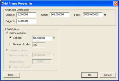
The sign conventions of the conceptual model and GenCade model are different. When a user creates a grid in the conceptual model, the Grid Frame Properties window will list Angle under Origin and Orientation. In the conceptual model, the sign convention is in degrees counterclockwise from the x axis. This is the angle listed under Grid Frame Properties. However, this is not the angle that will be used to set up the wave direction for the wave information.
Once the conceptual model is converted to 1D grid, cell numbers will be used instead of real world coordinates. In the GenCade model, the sign convention is also different. The sign convention is in degrees clockwise from north. Wave data must be relative to the orientation of the GenCade model grid and not the conceptual model grid. While working in the GenCade model, go to GenCade in the top menu and click on Edit Grid. The Origin X, Origin Y, Number of cells, and Cell size will be the same as specified in the conceptual model. The Azimuth is different than the Angle specified in the conceptual model. The wave directions must be relative to this Azimuth.
The following section will list steps to correctly define wave direction for GenCade.
Setting Up Wave Data in GenCade
This section will go through all of the steps to set up wave data correctly in GenCade by going through a simple example. This will be an idealized case, but this should give the user a better understanding of the sign conventions.
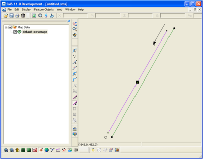
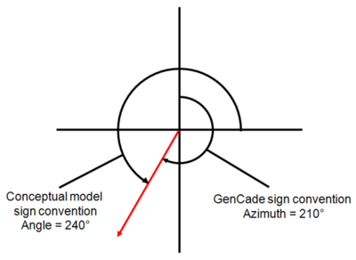
For this simple idealized setup, Origin X and Origin Y are zero, the I size is 5000 ft, and the Angle is 240. The conceptual model setup is shown in Figure 1, and the Grid Frame Properties are shown in Figure 2. As mentioned previously, the Angle assigned in the conceptual model is not the orientation used to determine wave direction. Since the waves are input in the conceptual model, there are two ways to ensure the directions used are correct. The first way is to convert to 1D grid and click on Edit Grid and check the Azimuth. In this case, the Azimuth is 210. Delete the GenCade grid to return to the conceptual model. The second way to determine the azimuth is to calculate it. To do this, it is necessary to understand the sign conventions in the conceptual model and the GenCade model. The sign convention for the conceptual model is in degrees counterclockwise from the x axis. The sign convention for the GenCade model is in degrees clockwise from north. This is shown in Figure 3. For the grid orientation in the example, the angle is 240 degrees with the conceptual model sign convention, and the azimuth is 210 degrees with the GenCade sign convention.


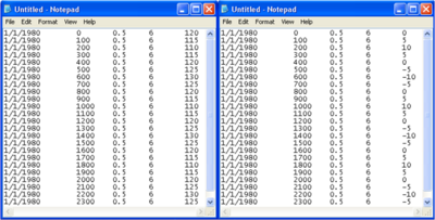
The waves used in GenCade must be shore (grid) normal based on the GenCade grid orientation. In this example, the orientation of the grid is 210 degrees. This means that converted to shore normal, a wave direction of 0 degree angle in GenCade would have a direction of 120 degrees from north. A wave direction 10 degrees in GenCade would have a direction of 110 degrees from north, while a wave direction of -10 degrees in GenCade would have a direction of 130 degrees from north. Please remember that the wave direction in GenCade must be between -90 and +90 degrees. When the direction is coming from land in the raw wave data, it is necessary to make the wave height and direction zero in GenCade. Figure 4 compares the wave direction from north to the wave direction entered in GenCade. The first through fourth columns are date, time, wave height, and wave period, respectively. The fifth column is wave direction from north and wave direction as input in GenCade.
