CMS
The Coastal Modeling System
The Coastal Modeling System (CMS) has been a research and development area of The Coastal Inlets Research Program (CIRP) at the United States Army Corps of Engineers - Engineering Research and Development Center (USACE-ERDC), Coastal and Hydraulics Laboratory (CHL) since 2006. It was built from a group of numerical models that have been under development since 2002. Information on the CIRP and publications on the CMS can be found at the CIRP Website.
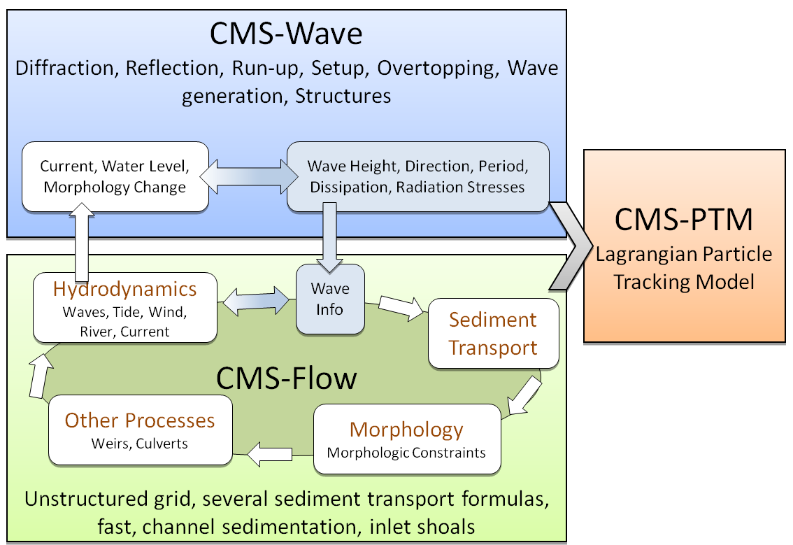
The system is a coordinated system of major multidimensional numerical models integrated to simulate waves, currents, water level, sediment transport, and morphology change in the coastal zone. Emphasis is on navigation channel performance and sediment exchanges between the inlet and adjacent beaches in the coastal zone. The CMS has been verified with field and laboratory data.
System Components
The system is composed of three main components: CMS-Flow, CMS-Flow, and CMS-PTM.
The Coastal Modeling System (CMS), developed under the U. S. Army Corps of Engineers Coastal Inlets Research Program, is designed for practical applications in navigation channel performance and sediment management for coastal inlets and adjacent beaches in order to improve the usage of Operation and Maintenance Funds. The CMS is intended as a research and engineering tool that can be used by novice and experienced modelers on desk-top computers and can be also run in parallel using OpenMP. The CMS takes advantage of the Surface-water Modeling System (SMS) interface for grid generation and model setup, as well as plotting and post-processing (ZUNDEL, 2000). The circulation model in the CMS (namely CMS-Flow) computes the unsteady water level and current velocity fields by solving the depth-averaged 2-D shallow water flow equations on a non-uniform Cartesian grid with an explicit finite volume scheme. The model can simulate tide, wind and wave driven currents, and includes the Coriolis force, wind stress, bottom friction, and wave radiation stresses. The primary variables are defined on a staggered pattern, i.e. the water surface level is calculated at the cell center, whereas the x- and y-components of the velocity are at the left and bottom faces of the cell, respectively. Further details of the flow model refer to BUTTOLPH et al. (2006). The spectral wave transformation model used in the CMS (namely CMS-Wave) solves the steady-state wave-action balance equation on a non-uniform Cartesian grid with a finite difference scheme. It considers wind wave generation and growth, diffraction, reflection, dissipation due to bottom friction, whitecapping and breaking, wave-wave and wave-current interactions, wave runup, wave setup, and wave transmission through structures. The wave diffraction is based on the parabolic wave approximation equation suggested by MASE et al. (2005). The CMS-Wave is a half-plane model which assumes waves only propagate from the offshore boundary towards shore. Reflected waves are calculated with a backward marching routine. Additional details on the wave model refer to MASE et al. (2005) and LIN et al. (2008). The existing sediment transport model in the CMS has two options. One option is a total-load formulation that solves the Exner equation for bed change, and the other option solves the suspended-load transport (advection-diffusion) equation and the bed-load mass balance equation (BUTTOLPH et al. 2006). Both options belong to equilibrium transport model. To enhance the performance of the CMS, the non-equilibrium sediment transport model is implemented in this study. The methodologies and merits of this model are described in the following sections.
For additional information on each component of the CMS select one of the links below:
Steering
In order to combine the capabilities of the two main numeric engines of Flow and Waves, the user must pass information from one engine to the other. In the case of CMS-Flow, this means reading in wave data from CMS-Wave. Information passed to CMS-Flow includes reading radiation stress gradients that directly impact currents (wave driven currents) and height fields, wave directions and breaking data which enter into the sediment transport rate formulations. In the case of CMS-Wave, the option exists to read in currents and simulate their transformation by the current. For either situation, the data fields must be interpolated onto the native domain (interpolate wave data onto the flow grid and/or flow data onto the wave grid).
This may be done interactively using the tools in SMS. However, it is much more efficient to read or define simulations for both engines, and invoke the steering module from the Data menu. This tool runs the engines separately, but interpolates the output and passes it to the other engine automatically.
External Links:
- US Army Engineer Research and Development Center - Ongoing Research [1]
- Presentations
- Aug 2008 Two-Dimensional Depth-Averaged Circulation Model CMS-M2D: Version 3.0, Report 2, Sediment Transport and Morphology Change [7]
{{#rawmsg:back}}
