Profile Feature Extraction: Transect and Baseline Creation
Baselines and transects are the foundational method by which the Profile Feature Extraction toolbox operates. The Transect Editor Toolbox is used for consistent transect creation to be leveraged by both the Profile Feature Extraction Toolbox and the Quick Response Toolbox, as well as other JALBTCX framework tools.

The user begins by manually digitizing a baseline. Creation of a line feature class and manual digitization is completed using base level ArcGIS Pro tools in combination with imagery and DEM source data – this imagery can be user provided or based on the base maps provided by ArcGIS Pro. The goal for baselines as they relate to the Profile Feature Extraction Toolbox is to select the landward limit, often the first line of infrastructure. This first line of infrastructure may include items such as coastal roadways, buildings, or even vegetation lines. The baseline is expected to be drawn nearly shore parallel, although various tools in the Transect Editor Toolbox provide standardized methods to adjust for normal digitizing inconsistencies, such as the “TE 00: Smooth Baseline” tool. Regardless, a properly drawn baseline that does not include sharp curves can greatly benefit the transect creation process by reducing overlapping and ensuring transects are perpendicular to the shoreline.
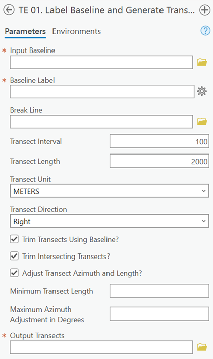
Once a smooth, shore parallel baseline is drawn along the landward limit, transects are generated extending from that baseline across the coastal zone. This is completed through the first step in the Transect Editor Toolbox, “TE 01: Label Baseline and Generate Transects”. This script labels the user-specified baseline file with segment information and generates transects at a specified spacing (interval) alongshore and at a specified length cross-shore. This script also allows for the trimming of transects, adjustment of transect azimuth, and specification of distance units, all seen as inputs in Figure 3.
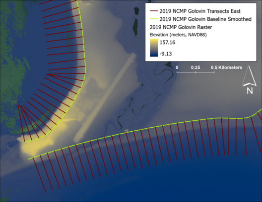
After creation of the transects, additional editing can be completed as needed in the remaining steps in the Transect Editor Toolbox. These steps include: “TE 01b: Adjust Transects by Moving Average”, “TE 01c: Rotate Transects”, “TE 01d: Diffuse Transects”, and “TE 01e: Trim Transects”. These tools are all optional and can be used on a sub selection of transects generated in the case that only a small number of transects need adjusting. Figure 4 displays a portion of the baseline and transects generated in Golovin, AK.
