Profile Feature Extraction: Step 2a - Extract Profile and Plot

Summary: This step extracts morphology features and plots each cross-shore profile view by leveraging the point output from Step 1 and a set of user values. The output of this step includes a point feature class containing the elevation and cross-shore location for each extracted profile feature (e.g., dune crest, dune toe, back trough, MHW, etc.) along each transect as well as cross-shore profile plots.
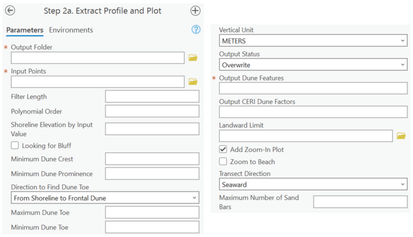
Output Folder: The full file path of the folder to contain the output cross-shore profile plots.
Input Points: The elevation point feature class generated in Step 1.
Filter Length: A positive odd integer value greater than the polynomial order that specifies the cross-shore length that the profiles will be smoothed by. In combination with the polynomial order, this helps reduce noise in the input profiles when detecting profile features. A Savitzky-Golay filter is used to smooth the profile as needed.
Polynomial Order: A positive integer value smaller than the filter length that specifies what order of polynomial best represents the input profiles. For example, a third order polynomial tends to be shaped like a single dune feature, while higher orders may represent multi-dune profiles. In combination with the filter length, this helps reduce noise in the input profiles when detecting profile features.
Shoreline Elevation by Input Values: The desired shoreline elevation relative to the zero datum of the input DEM. This value is site specific and is directly used to extract the shoreline point, from which all other points are detected.
Looking for Bluff: Checkbox to indicate if a search for bluff features should occur, for geological areas where coastal bluffs are a significant morphological feature.
Minimum Bluff Elevation, Maximum Bluff Toe: User defined values that aid the tool in searching for bluff features. Estimated values are specific to the study site. During the QA/QC process, these values will likely need to be adjusted multiple times to best constrain the elevation range of bluff features. These options are only available if the “Looking for Bluff” box is checked.
Minimum Dune Crest, Minimum Dune Prominence, Minimum/Maximum Dune Toe: User defined values that aid the tool in searching for morphology features.
Direction to Find Dune Toe: The direction the tool will use to detect the dune toe. Shoreline to frontal dune starts at the shoreline and moves landward to search for the dune toe; frontal dune to shoreline starts at the frontal dune crest point and moves seaward to search for the dune toe.
Vertical Unit: The vertical unit for elevations stored in the points from Step 1, either feet or meters. If a conversion from one unit to another is desired, that may also be selected (e.g., FEET2METERS). The vertical unit must be consistent with the horizontal unit of the input point feature, so the conversion here should be used if necessary.
Output Status: The specification of either “Overwrite” or “Update” in relation to the saving of dune feature points, especially when dune features under the existing name already exist. “Update” appends the dune feature points table, keeping the previously generated data.
Output Dune Features: The desired name of the output extracted morphology features. The points will be written to the project .gdb by default.
Output CERI Dune Factors: The desired name of the output CERI table. The table will be written to the project .gdb by default. This output is optional unless the user wants to calculate CERI.
Landward Limit: A polyline input feature that defines a landward limit location. By default, the landward limit of the profiles and CERI calculations is the baseline end of each transect.
Add Zoom-in Plot: A check box to generate a secondary plot that extends from the landward limit to the shoreline. By default, plots are generated from the landward limit to the end of each transect. If checked, the “Zoom to Beach” option appears.
Zoom to Beach: When the “Add Zoom-in Plot” box is checked, a checkbox appears to generate an additional plot that extends from the dune toe to the shoreline.
Transect Direction: Indication to the toolbox which way the transect is directed based on how it was generated. Seaward indicates a transect that extends from a landward baseline towards the sea while landward indicates a transect that extends landward from a sea baseline. Use elevation attempts to detect the direction based on the slope values around the MHW point.
Maximum Number of Sand Bars: An integer that specifies the largest number of sandbars that will be selected along each transect. The toolbox detects all sandbars and then keeps the specified number of sandbars based on prominence, eliminating the least prominent sandbars. A zero value will eliminate searching for sandbar features.
Best Practices:
1. MHW data can be obtained from nearby water level gauges or the NOAA VDatum website.
2. Estimated elevation values are specific to the study site. During the QA/QC process, these values will likely be adjusted multiple times to best constrain the elevation ranges of bluff and dune features.
3. The “Direction to Find Dune Toe” input may be a trial and error process for each location, but typically the “shoreline to frontal dune” option is adequate.
4. It is recommended to make a copy of the profile feature class exports after Step 2a before manual edits are completed for backup and comparison purposes.
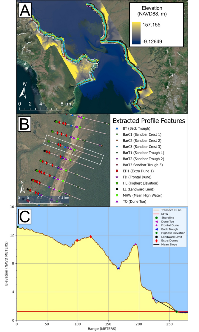
Figure 9 displays the output of Step 2a: Extract Profile and Plot for the Golovin, AK example data. Figure 9a displays the overall location with the DEM colormap legend and a white callout box. Figure 9b displays the data within the callout box, with another callout box displaying which transect is being displayed in Figure 9c. Note that the toolbox may select certain high elevation points as dunes (or, in this case, “extra dunes”) even if those points do not necessarily represent dune features. Manual quality assurance and control methods are leveraged after this step to resolve these issues.
