CMS-Flow Weir Structures
Introduction
A weir is an overflow structure built across a river or an open channel, allowing water to flow over the top. Weirs are commonly used for flow and flooding control and salinity and sediment management. Weirs are also constructed as nearshore coastal structures, such as weir jetties, to control longshore sediment transport, stabilize channel morphology, and protect harbors and navigation channels. In coastal applications, weirs represent unique features of solid structures and it is necessary to incorporate the structures into coastal hydrodynamic and sediment transport modeling systems.
Usage of Weirs for CMS in the SMS
Early SMS versions (< 13.4)
Previous documentation (Link given below) described the formulation and implementation of Weir structures in CMS, detailing input requirements for SMS versions up to 11.2. This implementation required hand-manipulation of the CMS-Flow parameter files to add in lists of cells and option values.
Future SMS versions (13.4.x)

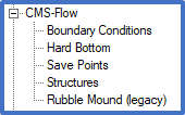
A "Structures" coverage has been added beneath the CMS-Flow model option in SMS 13.4 and later. This one coverage will handle Weir structures as well as three other types: Rubble Mounds, Culverts, and Tide Gates.
- Simply create a new feature arc within the new Structures coverage.
- Select the arc and double click the arc to open the dialog.
- Choose "Weir" for the type and then enter the needed information on the right side of the dialog.
- When finished, the "Structures" coverage will need to be applied to the CMS Simulation in order to export the appropriate cards to the parameter file.
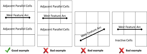
Present Requirements for ALL weir structure cells and adjacent cells parallel to the arc:
- Must all be ACTIVE (computational).
- Must have the same resolution.
- Must all exist in the same row or column.

CMS-Flow specific information for SMS 13.4+
The parameters/selections for each Weir structure polygon will be exported to the ‘.cmcards’ file in the form of a block of values. This implementation has been confirmed to work with CMS 5.4.0 and later.
- The Weir parameter cards needed for each structure are added to a block with a corresponding BEGIN/END statement for each weir are listed in the table below.
- For readability and to be consistent with other cards in the .cmcards file, all values should start in column 36 and a gap of 2 spaces before comments or the list of cell ids.
| Cardname | Indent 2
spaces? |
Type of value written | Notes |
|---|---|---|---|
| WEIR_STRUCT_BEGIN | NO | N/A | |
| CELL_IDS | YES | <int> <multiple int> | Total number of cells (n) followed by a list of all cell ids (from 1 to n). |
| DISTRIBUTION_COEFFICIENT | YES | <real> | |
| ORIENTATION_SEA | YES | 'NORTH', 'EAST', 'SOUTH', 'WEST' | Direction of sea |
| CREST_TYPE | YES | 'SHARP', 'BROAD' | Sharp-crested or Broad-crested |
| FLOW_COEFF_FROM_BAY | YES | <real> | |
| FLOW_COEFF_FROM_SEA | YES | <real> | |
| CREST_ELEVATION | YES | <real> | Positive is upward |
| METHOD | YES | 1 or 2 | 1= Approach 1, 2= Approach 2 (see literature) |
| WEIR_STRUCT_END | NO | N/A |
An example weir implementation is shown below. Line comments are preceded by a '!'.
WEIR_STRUCT_BEGIN
  CELL_IDS                           8  16864 16865 16866 16867 16868 16869 16870 16871
  DISTRIBUTION_COEFFICIENT           0.9
  ORIENTATION_SEA                    'SOUTH'
  CREST_TYPE                         'SHARP'
  FLOW_COEFFICIENT_FROM_BAY          0.05
  FLOW_COEFFICIENT_FROM_SEA          0.05
  CREST_ELEVATION                    -0.22
  METHOD                             2  !1= Approach 1, 2= Approach 2
WEIR_STRUCT_END

Example Case
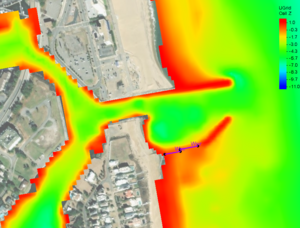
One example case for Weirs is described below and example files are provided in the next section. This example introduces a grid representative of Rudee Inlet. Two segments near the inlet on the south side designate the weir structures.
The grid and bathymetry is shown in the figure to the right with the weir structures identified by the feature arcs near the inlet.
Input and output files
Below are the prospective project and input/output files for SMS 13.4/CMS 5.4.0:
Last update 12/19/2024
Back to CMS-Flow Structures page
Back to Documentation Portal