CMS-PTM
Case Studies / Sample Problems
The following tutorials may be helpful for learning to use CMS-PTM in SMS:
Noyo Nearshore Sediment Placement Pilot Study
Noyo Harbor and Noyo River are located on the northern California coast. Every year about 30,000-40,000 cy of beach-quality sediment is dredged from the Noyo River Federal Navigation Channel. The USACE San Francisco District (SPN) and the Coastal and Hydraulics Laboratory (CHL), U.S. Army Engineer Research and Development Center are presently collaborating with the Noyo Harbor District and stakeholders in a pilot study to investigate a potential candidate site for nearshore placement of dredged sediment. Upland disposal sites used in the past will soon be exceeded. The pilot study proposes a dispersive nearshore site 3 to 8 miles north of Noyo Bay along the northern California coast (Figure 1).
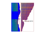
To evaluate the potential impacts of nearshore placement, the CMS and CMS-PTM were applied to simulate sediment transport for combined waves and currents under various ambient conditions and project alternatives. The model results will provide the technical information necessary to evaluate a demonstration site that is economically feasible for the optimum sediment placement location.
CMS-PTM
The CMS calculates water levels, currents and waves through the coupling of a hydrodynamic model, CMS-Flow and a wave spectral model, CMS-Wave. CMS-Flow is driven by time-dependent water surface elevation at the offshore open boundaries, and wind forcing over the surface boundary. Directional wave data for input to CMS-Wave are available from the National Data Buoy Center (NDBC, http://www.ndbc.noaa.gov) and Coastal Data Information Program (CDIP, http://cdip.ucsd.edu). The wave conditions are specified at the seaward boundaries.
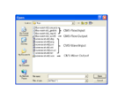
CMS-Flow requires three input files and CMS-Wave requires six input files through the SMS. Each of CMS-Flow and CMS-Wave simulations will generate its own output file (Figure 2). The CMS-Flow input and output files are required, while the CMS-Wave output files are optional for setting up a CMS-PTM simulation. After loading the required hydrodynamic and/or wave files, users can follow the steps below to set up the CMS-PTM simulation for the Noyo application.
- Native Sediment Dataset CMS-PTM requires spatially varying native bed sediment data specified as datasets, including the grain size information of d35, d50, and d90 for each cell, in the CMS-Flow grid.
- Select and open the CMS-Flow control file, “flow-exist-Alt2.cmcards” (Figure 2),
- Choose Data | Data Calculator in the CMS-Flow menu,
- Name the first dataset, d35, in the Output data set name and specify a constant value, 0.1 mm in the Calculator,
- Click Compute to generate the dataset,
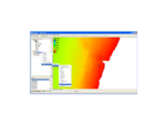
- Repeat steps iii) and iv) to generate the datasets for d50 and d90 (Figure 3), (for the Noyo simulation, d50=0.2 mm and d90=0.4 mm)
- Click Done to exit Data Calculator,
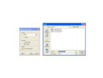
- Highlight the datasets, d35, d50, and d90, right-click, and select Export Datasets (Figure 4),
- Select XMDF file in the File Type, check All time steps in the Time Steps, and click the Filename to save the file “NativeSediments.h5” in the present working folder.

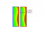
- Land-water Interface Boundary Strings CMS-PTM requires specifications of both open and closed boundaries. Open boundaries are specified in CMS-Flow so closed boundaries need to be added for CMS-PTM (future versions of SMS will automatically generate the closed boundaries). The steps to perform this task are described as follows:
- Choose Cellstring | Generate Along Boundary (this step will generate redundant boundary strings overlapped with existing strings along open boundaries) (Figure 5),
- Choose the Select Cellstring tool and select the Land boundary along the open boundary,
- Right click and choose Delete (Figure 5),
- Repeat steps ii) and iii) to delete other Land boundary cellstrings overlapped with existing open boundaries if more than one open boundaries exist in CMS-Flow,
- Save the project.
- Sediment Sources Particles can be released from different source options. In CMS-PTM, sediment sources can be specified as points, lines, or areas. For the Noyo application, an area source was designated to represent the nearshore placement of dredged materials from a barge. The steps for creating the source file in SMS are:
- Switch to the Map Module by clicking the icon,
- Right click the default coverage and choose Type | Models | PTM after generating the rectangular area for the sediment release (Figure 6),
- Choose the Select Feature Polygon icon and click on the area source,
- Right-click the polygon, select Attributes, and the Feature Object Attributes will pop up,
- Select the Horizontal Polygon Source in the Type (Figure 7),
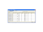
- Specify Date/Time for the particle release, Parcel Mass (kg), released mass Rate (kg/m2/s), and Median Grain Size (mm) of released particles (Figure 7),
- Save the area source specification as a map file.
- CMS-PTM Setup After the hydrodynamic data, native sediment data, source file, and boundary cellstrings are generated, users can follow steps below to specify the CMS-PTM parameters and set up the CMS-PTM simulation.
- Switch to Particle Module by clicking the icon ,
- Choose PTM | New Simulation,
- Choose PTM | Model Control.
- Indented line
- Simulation time (Figure 8)