CMS/DredgeModule/Phase2: Difference between revisions
mNo edit summary |
mNo edit summary |
||
| Line 1: | Line 1: | ||
Under construction. | <big>Under construction.</big> | ||
= Background = | = Background = | ||
The dredging and placement of multiple sediment grain-sizes are an extension of the single-grain | The dredging and placement of multiple sediment grain-sizes are an extension of the single-grain | ||
| Line 17: | Line 17: | ||
a simulation due to erosion and deposition. Guidance on the implementation in SMS is available at [[CMS-Flow_Multiple-sized_Sediment_Transport | CMS-Flow_Multiple-sized_Sediment_Transport]]. | a simulation due to erosion and deposition. Guidance on the implementation in SMS is available at [[CMS-Flow_Multiple-sized_Sediment_Transport | CMS-Flow_Multiple-sized_Sediment_Transport]]. | ||
= | The CMS is a depth-averaged numerical model. Because the effects of three-dimensional | ||
The | processes are not included in the dredging and placement module, dredged cut and placement | ||
features are not reflective of realistic morphology around designated operation sites. Therefore, | |||
this module is suggested to be applied in cases with non-cohesive sand sized sediment where the | |||
morphological characteristics of dredging/placement need not be resolved. | |||
= Setup = | |||
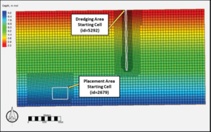
The grid, bathymetry, and dredging and placement areas for the example simulation are shown in | |||
Figure 1, which represents a typical offshore region extending 6 kilometers (km) along shore and | |||
3 km offshore, with water depths on the order of 1.5 m in the nearshore and 9 m at the offshore | |||
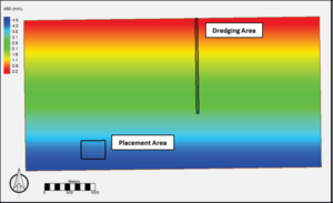
extent. The bed composition is shown in Figure 2. The median grain size (d50) is 0.2 millimeters | |||
(mm) in the nearshore and increases linearly offshore, to a value of 3.0 mm. | |||
[[File:DM_P2_Fig1.png|thumb|300px|Figure 1. CMS grid, bathymetry and Dredge Module information.]] | |||
[[File:DM_P2_Fig2.png|thumb|300px|Figure 2. Initial distribution of the d50 values of the bed.]] | |||
The dredging and placement areas simulated in Examples 1, 2, and 3 are illustrated in Figure 1. The dredging area is 60 m wide by 1,880 m long (area = 112,800 m<sup>2</sup>) extending from the nearshore to a depth of approximately 6.0 m. The dredged depth is specified as 6.0 m. This yields a total dredged volume of 220,465 m<sup>3</sup> of bulk material. The dredging rate is specified as 10,000 m<sup>3</sup> per day corresponding to a 22-day dredging event. The dredging is specified to start at the nearshore and proceed in the offshore direction by specifying the starting cell locations (as indicated in Figure 1). The placement area is located offshore of the dredging area and is 400 m by 520 m (area =208,000 m<sup>2</sup>). Two dredging methods were tested in Examples 1 and 2, and Example 3 applied a variation of bed layer thickness for comparison to Example 2. | |||
= Example 1 = | |||
Revision as of 16:31, 30 January 2024
Under construction.
Background
The dredging and placement of multiple sediment grain-sizes are an extension of the single-grain size transport approach. In the updated Dredge Module, the sediment can be represented by discrete grain size classes, and each size class is eroded, transported, and deposited independently. The grain size classes interact solely in the bed layers. The bed is represented by sediment layers of a specific thickness below the bed surface. The top or surficial upper bed layer is referred to as the mixing layer (often referred to as the active layer), which exchanges the surficial sediments with deposition from the water column. The mixing layer thickness may be set to a constant value (e.g., 0.05 meter [m]) or calculated based on the median grain size and bed form size at each cell. The critical shear stress for erosion for each grain size class in the mixing layer is determined using the hiding and exposure approach of Wu.
Below the mixing layer, additional bed layers are defined and are used to track the fraction of each grain size class in the bed, referred to as the bed composition. All of the bed layers exchange sediment with each other by splitting and merging adjacent layers as their thickness evolves during a simulation due to erosion and deposition. Guidance on the implementation in SMS is available at CMS-Flow_Multiple-sized_Sediment_Transport.
The CMS is a depth-averaged numerical model. Because the effects of three-dimensional processes are not included in the dredging and placement module, dredged cut and placement features are not reflective of realistic morphology around designated operation sites. Therefore, this module is suggested to be applied in cases with non-cohesive sand sized sediment where the morphological characteristics of dredging/placement need not be resolved.
Setup
The grid, bathymetry, and dredging and placement areas for the example simulation are shown in Figure 1, which represents a typical offshore region extending 6 kilometers (km) along shore and 3 km offshore, with water depths on the order of 1.5 m in the nearshore and 9 m at the offshore extent. The bed composition is shown in Figure 2. The median grain size (d50) is 0.2 millimeters (mm) in the nearshore and increases linearly offshore, to a value of 3.0 mm.
The dredging and placement areas simulated in Examples 1, 2, and 3 are illustrated in Figure 1. The dredging area is 60 m wide by 1,880 m long (area = 112,800 m2) extending from the nearshore to a depth of approximately 6.0 m. The dredged depth is specified as 6.0 m. This yields a total dredged volume of 220,465 m3 of bulk material. The dredging rate is specified as 10,000 m3 per day corresponding to a 22-day dredging event. The dredging is specified to start at the nearshore and proceed in the offshore direction by specifying the starting cell locations (as indicated in Figure 1). The placement area is located offshore of the dredging area and is 400 m by 520 m (area =208,000 m2). Two dredging methods were tested in Examples 1 and 2, and Example 3 applied a variation of bed layer thickness for comparison to Example 2.

