CR-07-1:Chapter4: Difference between revisions
*>Mitchell brown (Created page with ' ---- {|cellspacing=0 cellpadding = 10 |Chapter 3 - Bed Load | style=width:60% | | style=align-text:right|[[CR-07-1:Chapter5|Chapter 5 - Unifi...') |
No edit summary |
||
| Line 1: | Line 1: | ||
__TOC__ | |||
==Suspended load== | |||
===Introduction=== | |||
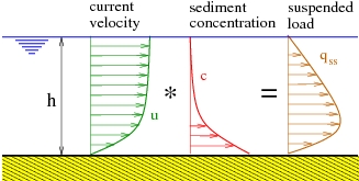
The earliest transport rate formulas are mainly based on the concept that the sediment transport rate for steady uniform flow can be related to the bottom shear stress (Meyer-Peter and Müller 1948; Einstein 1950; Engelund and Hansen 1972) assuming that bed-load transport prevails. However, if the shear stress is sufficiently large, the particles can be lifted, put in suspension, and transported in large quantities by the current. Thus, suspended load often prevails for fine sediments (''d''<sub>50</sub> < 0.5 mm). The traditional approach for calculating the unsteady depth-averaged volumetric suspended load transport ''q''<sub>''ss''</sub> is to determine the vertical distribution of suspended sediment concentration (''c'') and velocity (''u''), after which the product between these two quantities is integrated through the vertical from the edge of the bed-load layer (''z'' = ''z''<sub>''a''</sub>) to the water surface (''z'' = ''h'') (Van Rijn 1993), yielding: | |||
<math>{{q}_{ss}}\left( t \right)=\int_{{{z}_{a}}}^{h}{u\left( z,t \right)c\left( z,t \right)dz}</math> | |||
:(111) | |||
where ''q''<sub>''ss''</sub>(''t'') is the depth-averaged instantaneous suspended load per unit width, ''u''(''z'',''t'') and ''c''(''z'',''t'') are, respectively, the horizontal velocity and the volume sediment concentration at the height ''z'', ''z''<sub>''a''</sub> is the level at the top of the bed-load layer, and ''h''(''t'') is the instantaneous water depth. A steady situation is typically assumed to simplify the problem, so time-averaged values | |||
<math>u\left( z \right)=\overline{u\left( z,t \right)}</math> | |||
and | |||
<math>c\left( z \right)=\overline{c\left( z,t \right)}</math> | |||
are substituted (Figure 39): | |||
<math>{{q}_{ss}}=\int_{{{z}_{a}}}^{h}{c\left( z \right)u\left( z \right)dz}</math> | |||
:(112) | |||
Therefore, an accurate estimation of the total suspended load requires accurate prediction of the mean current velocity and concentration profiles. | |||
[[Image:CR-07-1_Chapter4_01.jpg|framed|none]] | |||
'''Figure 39. Computation of suspended load over depth.''' | |||
In the marine coastal environment, the process of sediment transport becomes complex because of the presence of oscillatory flows and the interaction between steady and oscillatory flows. For longshore sediment transport, the effect of the short waves is typically modeled as an additional sediment stirring that increases the bed shear stress and the vertical mixing coefficient for the sediment in suspension (Bijker 1967; Watanabe 1982; Van Rijn 1993). | |||
To describe suspended load above the wave boundary layer, some refined mathematical approaches were proposed during the last decades with sophisticated turbulence closure models (Fredsøe et al. 1985; Davies 1990; Davies et al. 1997). However, the development of practical sediment transport models still has a strong empirical character and relies heavily on physical insight combined with quantitative data obtained through laboratory and field experiments. | |||
An essential part of morphodynamic computations for flow conditions involving suspended sediment transport is the use of a reference concentration as a bed boundary condition. Van Rijn (1984b) proposed that the reference concentration should be a function of the bed-load transport. Furthermore, the main controlling parameters for the suspended load are the settling velocity of the sediment ''W''<sub>''s''</sub>, and more specifically, the vertical sediment diffusion coefficient <sub>''v''</sub>. The latter is examined here and compared to the Van Rijn (1984b) results. | |||
In the nearshore, for mild wave conditions, the bed is covered by ripples. These bed forms strongly affect the sediment transport by enhancing the suspended load, but also by modifying the direction of the sediment transport. Assuming | |||
<math>u\left( z,t \right)=\overline{u\left( z,t \right)}+\tilde{u}\left( z,t \right)=u\left( z \right)+\tilde{u}\left( z,t \right)</math> | |||
and | |||
<math>c\left( z,t \right)=\overline{c\left( z,t \right)}+\tilde{c}\left( z,t \right)=c\left( z \right)+\tilde{c}\left( z,t \right)</math> | |||
, where | |||
<math>\tilde{u}\left( z,t \right)</math> | |||
and | |||
<math>\tilde{c}\left( z,t \right)</math> | |||
are the oscillatory components, the net suspended sediment transport is obtained by averaging Equation 111: | |||
<math>{{q}_{ss}}=<\int_{{{z}_{a}}}^{h\left( t \right)}{\left[ u\left( z \right)c\left( z \right)+\tilde{u}\left( z,t \right)\tilde{c}\left( z,t \right) \right]}dz></math> | |||
:(113) | |||
<math>={{q}_{ss,c}}+{{q}_{ss,w}}</math> | |||
:(114) | |||
The first term on the right side (Equation 114) corresponds to the current-related suspended load, and the second term corresponds to the wave-related suspended load. The wave-related suspended load includes the quasi-steady suspended load due to asymmetric waves (assuming no phase lag exist between the wave velocity and the sediment concentration) and the unsteady effects due to a possible phase lag between the instantaneous velocity and concentration. Many experimental studies and most predictive models do not take into account the wave-related suspended load, although it appears to be significant for cross-shore sediment transport. | |||
The objective of this study was to develop a reliable and general formulation for the prediction of suspended load transport valid under a wide range of fluvial and coastal conditions. For this purpose, various data sets were used for the model development including steady and oscillatory flows. The study focused on the prediction of the sediment concentration through the water column, establishing relationships for the vertical sediment diffusivity and the reference concentration. Assuming a typical velocity profile, the current-related suspended load can easily be calculated. The second part of this study focused on the possible phase lag affecting the suspended load in the wave direction due to the presence of ripples. | |||
===Equilibrium profile for suspended sediment=== | |||
====Mass conservation equation==== | |||
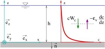
An equilibrium can exist between the settling velocity and the hydrodynamic forcing (Figure 40). The equation for the sediment concentration is derived from the mass conservation equation employed to compute changes in bottom topography: | |||
<math>\frac{\partial c}{\partial t}+\text{div}\vec{F}=0</math> | |||
:(115) | |||
with | |||
<math>\vec{F}={{\vec{F}}_{a}}+{{\vec{F}}_{s}}+{{\vec{F}}_{d}}</math> | |||
:(116) | |||
where ''c'' is the sediment volume concentration (dimensionless), and ''F'' is the total sediment flux (consisting of contributions from advection, settling, and diffusion): | |||
<math>\begin{align} | |||
& {{{\vec{F}}}_{a}}=c\ \vec{u}+c\ w\ {{{\vec{e}}}_{z}} \\ | |||
& {{{\vec{F}}}_{s}}=-c\ {{W}_{s}}\ {{{\vec{e}}}_{z}} \\ | |||
& {{{\vec{F}}}_{d}}=-{{\varepsilon }_{h}}\ \overrightarrow{\text{gra}{{\text{d}}_{\text{h}}}}\left( c \right)-{{\varepsilon }_{\nu }}\frac{\partial c}{\partial z}{{{\vec{e}}}_{z}} \\ | |||
\end{align}</math> | |||
:(117) | |||
with | |||
<math>\vec{u}</math> | |||
the horizontal velocity vector, ''w'' the vertical velocity, | |||
<math>{{\vec{e}}_{z}}</math> | |||
the unit vector in the vertical, | |||
<math>\overrightarrow{\text{gra}{{\text{d}}_{\text{h}}}}=\partial /\partial x+\partial /\partial y</math> | |||
the horizontal gradient, and (<sub>''v''</sub> and (<sub>''h''</sub> the vertical and horizontal eddy diffusivity, respectively. | |||
The bottom boundary condition yields the following relationship: | |||
<math>-\left( {{{\vec{F}}}_{s}}+{{{\vec{F}}}_{d}} \right)\ \vec{n}=S</math> | |||
:(118) | |||
where | |||
<math>\vec{n}</math> | |||
is the unit vector perpendicular to the bottom, and ''S'' the erosion-deposition flux due to suspended load. | |||
[[Image:CR-07-1_Chapter4_02.jpg|framed|none]] | |||
'''Figure 40. Concentration profile for steady conditions.''' | |||
Several different expressions have been derived for the concentration profile, but most of them rely on the steady-state vertical diffusion equation (Figure 40). Under steady conditions ( | |||
<math>\partial c/\partial t=0</math> | |||
, | |||
<math>\text{div}{{\vec{F}}_{a}}=0</math> | |||
, | |||
<math>\overrightarrow{\text{gra}{{\text{d}}_{\text{h}}}}\left( c \right)=0\ \text{and}\ S=0</math> | |||
), Equation 115 may be simplified to: | |||
<math>\frac{\partial c\left( z \right)}{\partial z}+\frac{{{W}_{s}}}{{{\varepsilon }_{v}}}c\left( z \right)=0</math> | |||
:(119) | |||
Depending on the expression selected for <sub>''v''</sub> analytical solutions to Equation 119 of different type may be found. Thus, if | |||
<math>c\left( z={{z}_{a}} \right)={{c}_{a}}</math> | |||
, where ''z''<sub>''a''</sub> is the reference level (the maximum value of the computed roughness is often used): | |||
<math>c\left( z \right)={{c}_{a}}\exp \left( -\int_{{{z}_{a}}}^{z}{\frac{Ws}{{{\varepsilon }_{v}}}dz} \right)</math> | |||
:(120) | |||
====Schmidt number==== | |||
An eddy viscosity coefficient is employed for determining the mixing, or diffusion coefficient. However, the mixing of sediment is not completely analogous to the mixing of water. The vertical eddy diffusivity of particles <sub>''v''</sub> is then related to the vertical eddy viscosity <sub>''v''</sub> through the Schmidt number σ: | |||
<math>\sigma =\frac{{{\varepsilon }_{v}}}{{{\nu }_{v}}}</math> | |||
:(121) | |||
In principle, σ should be a constant, and σ = 1. Three different processes were listed by Rose and Thorne (2001) to explain a deviation from unity: | |||
* The first process to explain a σ-values different from unity was proposed by Sumer and Deigaard (1981) and Van Rijn (1984b). They hypothesized that the centrifugal force in a fluid eddy causes sediment grains to be thrown outside of the eddy, which increases σ. | |||
* Another reason presented by Fredsøe and Deigaard (1994, pp. 231-234) for σ to deviate from unity might be sediment settling out of the surrounding water before the water loses its earlier composition by mixing. This effect is particularly significant for the high concentration of cohesive sediments. Lees (1981) showed that σ displayed a decreasing trend with increasing suspended sediment concentration. | |||
* Rose and Thorne (2001) added that the estimation of σ may be affected by the settling velocity, which varies because of the presence of turbulence. | |||
Based on measurements by Coleman (1981), Van Rijn (1984b) suggested the following expression for σ, which was defined as the ratio between the maximum sediment diffusivity and the maximum fluid eddy viscosity ( | |||
<math>\sigma ={{\varepsilon }_{v,\max }}/{{\nu }_{v,\max }}</math> | |||
with | |||
<math>{{\nu }_{v,\max }}=0.25\ \kappa {{u}_{*}}h</math> | |||
for a parabolic profile): | |||
<math>\sigma =1+2{{\left( \frac{{{W}_{s}}}{{{u}_{*}}} \right)}^{2}}\text{ with }0.1<\frac{{{W}_{s}}}{{{u}_{*}}}<1</math> | |||
:(122) | |||
====Sediment diffusivity and concentration profiles==== | |||
The sediment diffusivity <sub>''v''</sub> is a fundamental parameter for the estimation of the concentration profile, and it is a function of bottom roughness and shear stress, agitation (mainly due to waves), and settling velocity. Various distributions of the sediment mixing can be found in the literature, which typically produce either an exponential or a power-law sediment concentration profile. | |||
''Exponential profile''. If the sediment diffusivity <sub>''v''</sub> is constant (<sub>''v''</sub> 10<sup> 12</sup> m<sup>2</sup>/sec), an exponential profile is obtained for the mean concentration: | |||
<math>c\left( z \right)={{c}_{R}}\exp \left( -\frac{{{W}_{s}}}{{{\varepsilon }_{v}}}z \right)</math> | |||
:(123) | |||
where ''c''<sub>''R''</sub> is the reference concentration. The ratio ''W''<sub>''s''</sub>/<sub>''v''</sub> determines suspension conditions: | |||
if ''W''<sub>''s''</sub>/<sub>''v''</sub> > 4: weak suspension, | |||
if ''W''<sub>''s''</sub>/<sub>''v''</sub> < 0.5: strong suspension. | |||
The sediment diffusivity is often described as a function of the shear velocity and the water depth according to: | |||
<math>{{\varepsilon }_{v,E}}={{\sigma }_{E}}\ \kappa \ {{u}_{*}}\ h</math> | |||
:(124) | |||
where κ is Von Karman's constant (κ = 0.41), and σ<sub>''E''</sub> a constant consistent with the Schmidt number σ. | |||
''Power-law profile''. In the coastal zone, <sub>''v''</sub> is typically not expected to be constant over the depth, but a function of the agitation (mainly due to waves), bottom roughness, and settling velocity. For suspended sediment in a steady current, Rouse (1938) proposed a linear equation for the sediment diffusivity: | |||
<math>{{\varepsilon }_{v,P}}={{\sigma }_{P}}\ \kappa \ {{u}_{*}}\ z</math> | |||
:(125) | |||
with σ<sub>''P''</sub> being a constant consistent with the Schmidt number σ that Rouse assumed equal to 1. This expression, nowadays widely used, gives the following expression for the concentration profile over depth: | |||
<math>c\left( z \right)={{c}_{a}}{{\left( \frac{z}{{{z}_{a}}} \right)}^{-{{W}_{s}}/{{\sigma }_{p}}\kappa {{u}_{*}}}}</math> | |||
:(126) | |||
The parameter ''P''<sub>''R''</sub> = ''W''<sub>''s''</sub>/(κ''u''<sub>*</sub>) is commonly referred to as the Rouse parameter. It determines the shape of the suspended sediment profile, whereas the reference concentration ''c''<sub>''a''</sub> determines the magnitude of sediment in suspension at the reference level ''a'': | |||
* ''P''<sub>''R''</sub> > 5: near-bed suspension (''h''/10). | |||
* 5 > ''P''<sub>''R''</sub> > 2: suspension through bottom half of boundary layer. | |||
* 2 > ''P''<sub>''R''</sub> >1: suspension throughout the boundary layer. | |||
* 1 > ''P''<sub>''R''</sub>: uniform suspension throughout the boundary layer. | |||
The Rouse expression may be extended to a parabolic equation for the sediment diffusivity: | |||
<math>{{\varepsilon }_{v,B}}={{\sigma }_{B}}\ \kappa \ {{u}_{*}}\ z\left( 1-\frac{z}{h} \right)</math> | |||
:(127) | |||
where σ<sub>''B''</sub> is a constant consistent with the Schmidt number σ. This expression implies the following solution for concentration profile over the depth: | |||
<math>c\left( z \right)={{c}_{a}}{{\left( \frac{z}{h-z}\frac{h-{{z}_{a}}}{{{z}_{a}}} \right)}^{-{{W}_{s}}/{{\sigma }_{B}}\kappa {{u}_{*}}}}</math> | |||
:(128) | |||
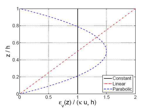
Because <sub>''v''</sub> varies over the depth, different values for σ<sub>''E''</sub>, σ<sub>''P''</sub>, and σ<sub>''B''</sub> are obtained depending on the chosen profile. Figure 41 plots the three different analytic profiles (Equations 124, 125, and 127) with σ<sub>''E''</sub> = 1/2σ<sub>''P''</sub> = 1/6σ<sub>''B''</sub> assuming that the constant value for the sediment diffusivity was obtained from an average over the depth for the linear profile and the parabolic profile. | |||
''Experimental estimation of sediment diffusivity profile''. If reliable point-concentration measurements are available, <sub>''v''</sub> may be calculated from (Vanoni 1946): | |||
<math>{{\varepsilon }_{v}}=\frac{-{{W}_{s}}c}{dc/dz}</math> | |||
:(129) | |||
However, experimental estimation of the sediment concentration often induces non-negligible errors because in most situations a maximum of 10-15 points is available over the depth, implying that the estimated slope of the resultant curve is subject to large discrepancies. | |||
In the following, the subscript ''v'' to indicate a vertical diffusivity will be dropped to simplify the notation. | |||
[[Image:CR-07-1_Chapter4_03_16.png|framed|none]] | |||
'''Figure 41. Three analytical relationships for vertical sediment diffusivity (Equations 124, 125, and 127) versus ''''''''z''''''''/''''''''h'' ''''''with σ = σ'''<sub>'''''E''</sub> ''''''= 1/2σ'''<sub>'''''P''</sub> ''''''= 1/6σ'''<sub>'''''B'''''</sub>'''.''' | |||
===Sediment diffusivity due to steady current=== | |||
====Experimental data==== | |||
To investigate the sediment diffusivity profile in steady conditions, available data sets covering a wide range in conditions were compiled and analyzed. Table 15 summarizes these data sets, where the types of flow motion and sediment properties are listed. For all these experiments, sand with a relative density ''s'' = 2.65 was used. Most of these data sets were found in the SEDMOC (Van Rijn et al. 2001) data compilation. | |||
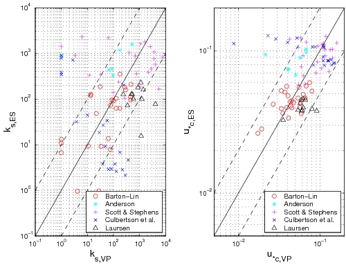
Using the data sets summarized in Table 15, the shear velocity can be calculated from the measurements of the energy slope, but also directly from the measurements of the velocity profile. Figure 42 compares these two methods of computing the shear velocity. Even if a correlation is observed, a large scatter exists (see also Camenen et al. 2006). The energy slope method appears to be more consistent, because the calculation of the shear velocity from the velocity profile shows more scatter (the number of measurement points in the velocity profile is often limited, particularly close to the bottom). | |||
'''Table 15. Data summary for suspended sediment experiments under steady currents. ''' | |||
{|border="2" cellspacing="0" cellpadding="4" width="100%" align="center" | |||
|'''Author(s)''' | |||
|'''Location''' | |||
|'''Flow Type''' | |||
|'''Number''' | |||
|'''''d'''''<sub>'''50</sub> ''''''(mm)''' | |||
|'''''b'' ''''''(m)''' | |||
|'''''F'''''<sub>'''''r''</sub> ''''''(-)''' | |||
|'''''U'''''<sub>'''''*c''</sub> ''''''(m/sec)''' | |||
|- | |||
|Anderson (1942) | |||
|Enoree River, USA (1940-41) | |||
|River data | |||
|23 | |||
|0.7 | |||
|15 | |||
|0.15-0.25 | |||
|0.02-0.07 | |||
|- | |||
|Barton & Lin (1955) | |||
|Fort-Collins, USA | |||
|Tilting flume | |||
|26 | |||
|0.18 | |||
|1.2 | |||
|0.2-0.9 | |||
|0.02-0,08 | |||
|- | |||
|Laursen (1958) | |||
|Iowa, USA (1961-63) | |||
|Tilting flume | |||
|12 | |||
|0.4, 1 | |||
|0.9 | |||
|0.25-0.60 | |||
|0.02-0.09 | |||
|- | |||
|Scott & Stephens (1966) | |||
|Mississippi River, USA (1961-63) | |||
|River | |||
|23 | |||
|0.4 | |||
|500 | |||
|0.11-0.16 | |||
|0.05-0.13 | |||
|- | |||
|Culbertson et al. (1972) | |||
|Rio Grande River, USA (1965-66) | |||
|River | |||
|22 | |||
|0.18-0.33 | |||
|20 | |||
|0.3-0.6 | |||
|0.05-0.15 | |||
|- | |||
|Voogt et al. (1991) | |||
|Krammer Beach, The Nederlands (April 1987) | |||
|Tidal channel | |||
|60 | |||
|0.22-0.35 | |||
|300 | |||
|0.1-0.5 | |||
|0.03-0.15 | |||
|- | |||
|Damgaard et al. (2003) | |||
|Wallingford, Great Britain | |||
|Duct experiments | |||
|24 | |||
|0.08-0.20 | |||
|0.6 | |||
|0.2-0.4 | |||
|0.01-9.14 | |||
|}<br clear="all"> | |||
[[Image:CR-07-1_Chapter4_04.jpg|framed|none]] | |||
'''Figure 42. Comparison between "energy slope" (ES) method and "velocity profile" method (VP) to estimate the Nikuradse roughness ''''''''k'''''<sub>'''''s''</sub> ''''''and shear velocity ''''''''u'''''<sub>'''''*c'''''</sub>'''.''' | |||
The experimental values obtained from each sediment concentration profile in the data sets are plotted (Figure 43) using Equation 129 and a point-by-point method yielding an estimate of the diffusivity according to: | |||
<math>{{\varepsilon }_{c,i}}=\frac{-{{W}_{s}}c(i)}{\left\{ c\left( i+1 \right)-c\left( i-1 \right)/\left[ z\left( i+1 \right)-z\left( i-1 \right) \right] \right\}}</math> | |||
:(130) | |||
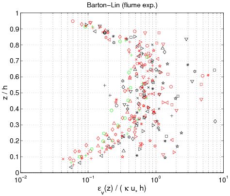
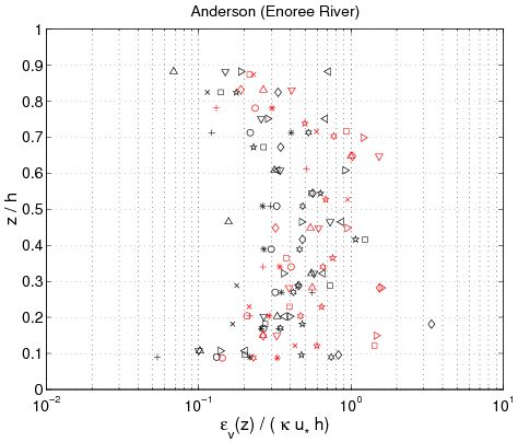
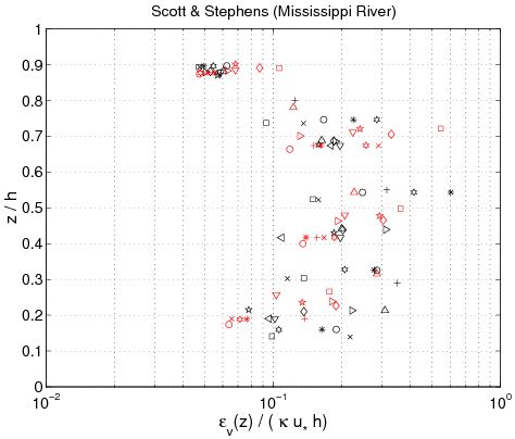
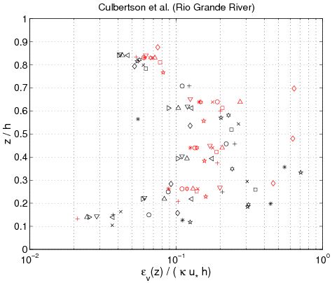
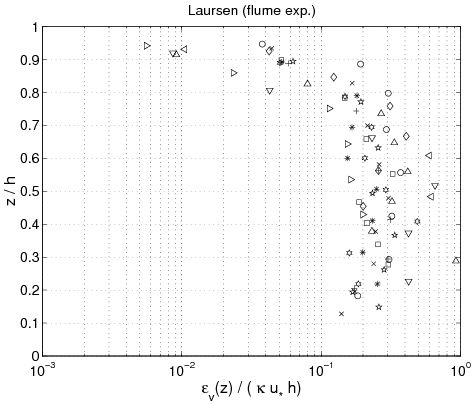
where ''i'' + 1 indicates consecutive experimental points along the z-axis for the concentration profile, and <sub>''c,i''</sub> is the estimated sediment diffusivity at level ''z'' = ''z''(''i''). Figure 43 confirms several results obtained previously. First, the sediment diffusivity is a linear function of the shear velocity ''u''<sub>''*c''</sub> and the water depth ''h''. Nevertheless, it appears that the mean values obtained for ''z'' ''h''/2 (where <sub>''c''</sub>. is not function of ''z''), depends on other parameters. Based on analysis of the different data set, the mean value varies from 710<sup> 2</sup> m<sup>2</sup>/sec to 1 m<sup>2</sup>/sec. Moreover, <sub>''c''</sub> appears to be an increasing function of ''z'' if | |||
<math>z/h\le 0.3</math> | |||
, a constant value for | |||
<math>0.3\le z/h\le 0.7</math> | |||
, and a decreasing function of ''z'' if | |||
<math>z/h\le 0.7</math> | |||
. Thus, referring to these results and the curves obtained in Figure 41, the best of the three analytic profiles previously discussed is the parabolic profile (Equation 127). Van Rijn(1984b) also proposed the following equations to compute the current-related sediment diffusivity: | |||
{|border="0" cellspacing="2" width="100%" | |||
| | |||
| | |||
[[Image:CR-07-1_Chapter4_05_257.png|framed|none]] | |||
|align = "right"|(131) | |||
|} | |||
Van Rijn (1984b) assumed that the sediment diffusivity is constant in the upper part of the water column. However, from the experimental results, a decrease is clearly observed if | |||
<math>z/h\le 0.7</math> | |||
. Equation 131, which produces a complex equation for the concentration profile, does not appear to improve the results compared to the parabolic profile. | |||
Finally, for the data sets from Voogt et al. (1991) and Damgaard et al. (2003), measurements of the energy slope were not made, and the calculation of the shear velocity from the velocity profile shows significant scatter. Therefore, results obtained for these two data sets are not presented in Figure 43. | |||
====Shape of concentration profile==== | |||
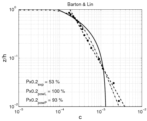
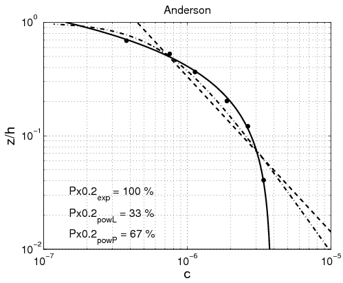
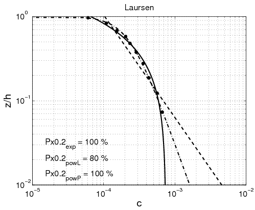
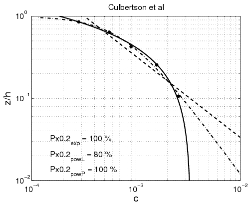
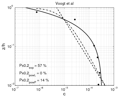
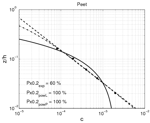
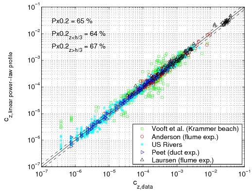
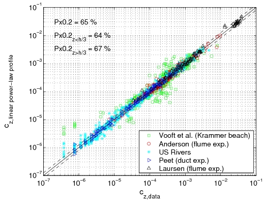
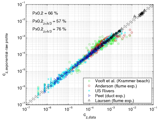
Power-law and exponential concentration profiles were fitted to the measurements (Table 15). For a power-law profile, both linear and parabolic sediment diffusivity were examined. Some typical examples of the fit for these profiles are presented in Figure 44 for each of the data sets. Table 16 lists the percentage of sediment concentration values predicted within a range of 20 percent error of the measurements presented for the different data sets (symbolized by ''pred''<sub>20,''meas''</sub>, ''pred''<sub>20,''powL''</sub>, and ''pred''<sub>20,''pow''</sub> for the fit of the exponential-law and the "linear" and "parabolic" power-laws, respectively in Figure 45). These calculations were also performed for sediment concentration data closer to the bed (''z ''< ''h''/3) and in the upper layer (''z'' > ''h''/3), where the velocity is approximately constant. | |||
{|border="2" cellspacing="0" cellpadding="4" width="100%" | |||
| | |||
[[Image:CR-07-1_Chapter4_06.jpg|framed|none]] | |||
| | |||
[[Image:CR-07-1_Chapter4_07.jpg|framed|none]] | |||
|- | |||
| | |||
[[Image:CR-07-1_Chapter4_08.jpg|framed|none]] | |||
| | |||
[[Image:CR-07-1_Chapter4_09.jpg|framed|none]] | |||
|- | |||
| | |||
[[Image:CR-07-1_Chapter4_10.jpg|framed|none]] | |||
| | |||
|} | |||
'''Figure 43. Vertical profile of sediment diffusivity obtained from Equation 129 using measured concentration profiles (each symbol corresponds to a particular profile).''' | |||
'''Table 16. Percentage of predictions of sediment concentration within +/- 20 percent of measured values obtained using an exponential law or power law <br>(linear and parabolic profile) for '''<sub>'''''''''c'</sub><sub>'</sub> ''''''in fitting against data. ''' | |||
{|border="2" cellspacing="0" cellpadding="4" width="100%" align="center" | |||
|align = "center" rowspan = "2"|'''Authors(s)''' | |||
|align = "center" colspan = "7"|'''Exponential-Law Profile (%)''' | |||
|align = "center"|'''Power-Law Profile (linear) (%)''' | |||
|align = "center"|'''Power-Law Profile (parab.) (%)''' | |||
|- | |||
|align = "center"|'''''z''''' | |||
|align = "center"|'''''z'' ''''''< ''''''''h''''''''/3''' | |||
|align = "center"|'''''z'' ''''''> ''''''''h''''''''/3''' | |||
|align = "center"|'''''z''''' | |||
|align = "center"|'''''z'' ''''''< ''''''''h''''''''/3''' | |||
|align = "center"|'''''z'' ''''''> ''''''''h''''''''/3''' | |||
|align = "center"|'''''z''''' | |||
|align = "center"|'''''z'' ''''''< ''''''''h''''''''/3''' | |||
|align = "center"|'''''z'' ''''''> ''''''''h''''''''/3''' | |||
|- | |||
|Barton & Lin | |||
|69.4 | |||
|51.1 | |||
|80.3 | |||
|85.7 | |||
|80.2 | |||
|89.1 | |||
|76.1 | |||
|67.8 | |||
|81.3 | |||
|- | |||
|U.S. Rivers | |||
|66.4 | |||
|60.3 | |||
|72.5 | |||
|62.1 | |||
|64.8 | |||
|59.5 | |||
|71.4 | |||
|71.4 | |||
|71.5 | |||
|- | |||
|Voogt et al. | |||
|46.6 | |||
|38.4 | |||
|62.2 | |||
|36.5 | |||
|37.6 | |||
|34.5 | |||
|48.9 | |||
|44.6 | |||
|57.1 | |||
|- | |||
|Damgaard | |||
|82.5 | |||
|82.5 | |||
|<nowiki>-</nowiki> | |||
|90.0 | |||
|90.0 | |||
|<nowiki>-</nowiki> | |||
|90.8 | |||
|90.8 | |||
|<nowiki>-</nowiki> | |||
|- | |||
|Laursen | |||
|96.9 | |||
|100 | |||
|95.8 | |||
|85.7 | |||
|85.2 | |||
|85.9 | |||
|92.9 | |||
|100 | |||
|90.1 | |||
|- | |||
|Total | |||
|65.6 | |||
|57.0 | |||
|75.8 | |||
|65.4 | |||
|63.5 | |||
|67.4 | |||
|69.9 | |||
|66.4 | |||
|74.1 | |||
|}<br clear="all"> | |||
---- | |||
{|border="2" cellspacing="0" cellpadding="4" width="100%" | |||
| | |||
[[Image:CR-07-1_Chapter4_11.jpg|framed|none]] | |||
| | |||
[[Image:CR-07-1_Chapter4_12.jpg|framed|none]] | |||
|- | |||
| | |||
[[Image:CR-07-1_Chapter4_13.jpg|framed|none]] | |||
| | |||
[[Image:CR-07-1_Chapter4_14.jpg|framed|none]] | |||
|- | |||
| | |||
[[Image:CR-07-1_Chapter4_15.jpg|framed|none]] | |||
| | |||
[[Image:CR-07-1_Chapter4_16.jpg|framed|none]] | |||
|} | |||
'''Figure 44. Examples of comparisons between predicted concentration profiles, using fitted exponential (solid line) or power-law profiles (dashed line), and measured concentration.''' | |||
---- | |||
{|border="2" cellspacing="0" cellpadding="4" width="100%" | |||
|align = "center"|<br>----<br>(a) | |||
|align = "center"|(b) | |||
|- | |||
| | |||
[[Image:CR-07-1_Chapter4_17.jpg|framed|none]] | |||
| | |||
[[Image:CR-07-1_Chapter4_18.jpg|framed|none]] | |||
|- | |||
|align = "center"|(c) | |||
|align = "center"| | |||
|- | |||
| | |||
[[Image:CR-07-1_Chapter4_19.jpg|framed|none]] | |||
| | |||
|} | |||
'''Figure 45. Comparison between predicted concentration using fitted exponential profile (a), "linear" power-law profile (b), or "parabolic" power-law profile (c), and measured concentration using all data.''' | |||
The main observation from this study is that there is no obvious law that fits all the measurements. However, the exponential law tends to yield better results for the upper part of the water column, whereas the linear power-law profile shows slightly better agreements closer to the bed. The parabolic power-law profile tends to produce better overall results as it presents nearly as good results as for the exponential profile in the upper part of the water column and even better results than the linear power-law profile in the lower part of the water column. This result confirms the idea of Van Rijn (1984b), who proposed an expression for the sediment diffusivity that linearly depends on the distance to the bed ''z'' close to the bed and is constant for ''z'' > ''h''/2. However, large differences between the two laws are found depending on the data set. Thus, the data sets obtained from Barton and Lin (1955) and Damgaard et al. (2003) are better described by a power-law profile, whereas the data sets obtained from Voogt et al. (1991) and Laursen (1958) exhibit better agreement with an exponential profile. All the data points are plotted (Figure 45) comparing predicted and measured sediment concentrations. It can be seen that larger discrepancy appears in using the power-law profile for the three U.S. rivers data sets, whereas larger discrepancy appears using the exponential law profile with the Barton and Lin (1955) data set. | |||
It should also be noted that the parabolic power-law profile produces a concentration equal to zero at the level ''z'' = ''h'', although the two other laws allows a non-zero value. In breaking waves, the sediment diffusivity is clearly different from zero at ''z'' = ''h'', which means that the parabolic power-law profile may not be used in the presence of breaking waves. For an expression that is applicable for both current and waves, the exponential law seems to be the most appropriate. | |||
====Estimation of Schmidt number==== | |||
Based on concentration profiles obtained from the compiled data set (Table 15), the fitted power-law and exponential profiles allow for an estimate of the Schmidt number. As discussed previously, the parabolic power-law profile for the sediment diffusivity <sub>''c''</sub> produces the best qualitative agreement with the observed profiles. For that reason, a good correlation between σ<sub>''B''</sub> and σ is expected, and σ<sub>''B''</sub> is calculated using Equation 128: | |||
<math>{{\sigma }_{B}}=\frac{-{{W}_{s}}}{{{\alpha }_{B}}\kappa {{u}_{*c}}}</math> | |||
:(132) | |||
where α<sub>''B''</sub> is the observed slope of the power-law relationship obtained by fitting to the data (the σ<sub>''P''</sub>-value is obtained in a similar manner). | |||
Some additional data were compiled (Table 17) from the studies by Rose and Thorne (2001), who also estimated σ<sub>c</sub> assuming a Rouse concentration profile, and from Van Rijn (1984b), who used the Coleman (1970)data. | |||
Combining data sets listed in Table 15 and the data listed in Table 17, a similar expression as the one Van Rijn (1984b) proposed was found (Figure 46): | |||
<math>{{\sigma }_{c}}\approx {{\sigma }_{B}}=0.6+6{{\left( \frac{{{W}_{s}}}{{{u}_{*c}}} \right)}^{2}}</math> | |||
:(133) | |||
'''Table 17. Data summary for analysis on Schmidt number (''''''''d'''''<sub>'''''''''s'</sub><sub>'</sub> ''''''corresponds to median grain size in suspension). ''' | |||
{|border="2" cellspacing="0" cellpadding="4" width="100%" align="center" | |||
|'''Author(s)''' | |||
|'''Location''' | |||
|'''Number''' | |||
|'''''d'''''<sub>'''''s''</sub> ''''''(m)''' | |||
|'''''U'''''<sub>'''''*C''</sub> ''''''(m/sec)''' | |||
|'''''h'' ''''''(m)''' | |||
|- | |||
|Coleman (1970) | |||
|Flume experiments | |||
|16 | |||
|1.49 - 2.10 10<sup>-4</sup> | |||
|0.02 - 0.06 | |||
|0.4 - 0.8 | |||
|- | |||
|Whitehouse (1995) | |||
|Thames estuary, UK | |||
|4 | |||
|9 10<sup>-5</sup> | |||
|0.56 - 0.61 | |||
|5 +/1 2 | |||
|- | |||
|Green et al. (1999) | |||
|Tanukau Harbour, NZ | |||
|2 | |||
|1.3 10<sup>-5</sup> | |||
|0.35, 0.45 | |||
|12-15 | |||
|- | |||
|Rose & Thorne (2001) | |||
|Taw estuary, UK | |||
|4 | |||
|1.2 1.3 10<sup>-4</sup> | |||
|0.41 - 0.63 | |||
|1.8 - 2.8 | |||
|}<br clear="all"> | |||
This equation produces a critical value for ''W''<sub>''s''</sub>/''u''<sub>''*c''</sub> 0.25, yielding σ<sub>''c''</sub> = 1. Up to this critical value, the centrifugal forces in the fluid eddies produce an increasing σ<sub>''c''</sub>. Equation 133 presents improved results compared to previous predictive formulas, as shown in Table 18 and Figure 46. | |||
'''Table 18. Prediction of Schmidt number using parabolic profile <br>or an exponential profile for steady current. ''' | |||
{|border="2" cellspacing="0" cellpadding="4" width="100%" align="center" | |||
|rowspan = "2"|'''Author(s)''' | |||
|align = "center" colspan = "7"|<br>'''<math>{{\sigma }_{c}}\approx {{\sigma }_{B}}</math>'''<br>''' (Equation 132)''' | |||
|align = "center"|<br>'''<math>{{\sigma }_{c}}\approx 6{{\sigma }_{E}}</math>'''<br>'''(Equation 135)''' | |||
|- | |||
|'''Px1.5 %''' | |||
|'''Px2 %''' | |||
|'''Mean (''''''''f''''''''('''<sub>'''''c'''''</sub>'''))''' | |||
|'''Std (''''''''f''''''''('''<sub>'''''c'''''</sub>'''))''' | |||
|'''Px1.5 %''' | |||
|'''Px2 %''' | |||
|'''Mean (''''''''f''''''''('''<sub>'''''c'''''</sub>'''))''' | |||
|'''Std (''''''''f''''''''('''<sub>'''''c'''''</sub>'''))''' | |||
|- | |||
|Van Rijn (Equation 123) | |||
|align = "center"|53 | |||
|align = "center"|78 | |||
|align = "center"|<nowiki>-</nowiki>0.02 | |||
|align = "center"|0.25 | |||
|align = "center"|54 | |||
|align = "center"|84 | |||
|align = "center"|<nowiki>-</nowiki>0.08 | |||
|align = "center"|0.22 | |||
|- | |||
|Rose & Thorne | |||
|align = "center"|58 | |||
|align = "center"|75 | |||
|align = "center"|0.02 | |||
|align = "center"|0.32 | |||
|align = "center"|63 | |||
|align = "center"|84 | |||
|align = "center"|<nowiki>-</nowiki>0.04 | |||
|align = "center"|0.27 | |||
|- | |||
|Equation 133 | |||
|align = "center"|52 | |||
|align = "center"|78 | |||
|align = "center"|0.03 | |||
|align = "center"|0.27 | |||
|align = "center"|68 | |||
|align = "center"|90 | |||
|align = "center"|<nowiki>-</nowiki>0.02 | |||
|align = "center"|0.19 | |||
|- | |||
|Equation 136 | |||
|align = "center"|50 | |||
|align = "center"|76 | |||
|align = "center"|<nowiki>-</nowiki>0.04 | |||
|align = "center"|0.26 | |||
|align = "center"|68 | |||
|align = "center"|88 | |||
|align = "center"|<nowiki>-</nowiki>0.09 | |||
|align = "center"|0.18 | |||
|}<br clear="all"> | |||
Using the exponential law to estimate the sediment diffusivity, for a steady current Equation 124 reduces to: | |||
<math>{{\varepsilon }_{c,E}}={{\sigma }_{E}}\ \kappa \ {{u}_{*c}}\ h\approx \frac{{{\sigma }_{c}}}{6}\kappa \ {{u}_{*c\ }}h</math> | |||
:(134) | |||
---- | ---- | ||
{|cellspacing=0 cellpadding = 10 | {|cellspacing="0" cellpadding = "10" | ||
|[[CR-07-1:Chapter3|Chapter 3 - Bed Load]] | |[[CR-07-1:Chapter3|Chapter 3 - Bed Load]] | ||
| style=width:60% | | | style="width:60%" | | ||
| style=align-text:right|[[CR-07-1:Chapter5|Chapter 5 - Unified Sediment Transport Formula for Coastal Inlet Applications]] | | style="align-text:right"|[[CR-07-1:Chapter5|Chapter 5 - Unified Sediment Transport Formula for Coastal Inlet Applications]] | ||
|} | |} | ||
[[category:Publications]] | [[category:Publications]] | ||
Revision as of 18:39, 13 July 2009
Suspended load
Introduction
The earliest transport rate formulas are mainly based on the concept that the sediment transport rate for steady uniform flow can be related to the bottom shear stress (Meyer-Peter and Müller 1948; Einstein 1950; Engelund and Hansen 1972) assuming that bed-load transport prevails. However, if the shear stress is sufficiently large, the particles can be lifted, put in suspension, and transported in large quantities by the current. Thus, suspended load often prevails for fine sediments (d50 < 0.5 mm). The traditional approach for calculating the unsteady depth-averaged volumetric suspended load transport qss is to determine the vertical distribution of suspended sediment concentration (c) and velocity (u), after which the product between these two quantities is integrated through the vertical from the edge of the bed-load layer (z = za) to the water surface (z = h) (Van Rijn 1993), yielding:
- (111)
where qss(t) is the depth-averaged instantaneous suspended load per unit width, u(z,t) and c(z,t) are, respectively, the horizontal velocity and the volume sediment concentration at the height z, za is the level at the top of the bed-load layer, and h(t) is the instantaneous water depth. A steady situation is typically assumed to simplify the problem, so time-averaged values
and
are substituted (Figure 39):
- (112)
Therefore, an accurate estimation of the total suspended load requires accurate prediction of the mean current velocity and concentration profiles.
Figure 39. Computation of suspended load over depth.
In the marine coastal environment, the process of sediment transport becomes complex because of the presence of oscillatory flows and the interaction between steady and oscillatory flows. For longshore sediment transport, the effect of the short waves is typically modeled as an additional sediment stirring that increases the bed shear stress and the vertical mixing coefficient for the sediment in suspension (Bijker 1967; Watanabe 1982; Van Rijn 1993).
To describe suspended load above the wave boundary layer, some refined mathematical approaches were proposed during the last decades with sophisticated turbulence closure models (Fredsøe et al. 1985; Davies 1990; Davies et al. 1997). However, the development of practical sediment transport models still has a strong empirical character and relies heavily on physical insight combined with quantitative data obtained through laboratory and field experiments.
An essential part of morphodynamic computations for flow conditions involving suspended sediment transport is the use of a reference concentration as a bed boundary condition. Van Rijn (1984b) proposed that the reference concentration should be a function of the bed-load transport. Furthermore, the main controlling parameters for the suspended load are the settling velocity of the sediment Ws, and more specifically, the vertical sediment diffusion coefficient v. The latter is examined here and compared to the Van Rijn (1984b) results.
In the nearshore, for mild wave conditions, the bed is covered by ripples. These bed forms strongly affect the sediment transport by enhancing the suspended load, but also by modifying the direction of the sediment transport. Assuming
and
, where
and
are the oscillatory components, the net suspended sediment transport is obtained by averaging Equation 111:
- (113)
- (114)
The first term on the right side (Equation 114) corresponds to the current-related suspended load, and the second term corresponds to the wave-related suspended load. The wave-related suspended load includes the quasi-steady suspended load due to asymmetric waves (assuming no phase lag exist between the wave velocity and the sediment concentration) and the unsteady effects due to a possible phase lag between the instantaneous velocity and concentration. Many experimental studies and most predictive models do not take into account the wave-related suspended load, although it appears to be significant for cross-shore sediment transport.
The objective of this study was to develop a reliable and general formulation for the prediction of suspended load transport valid under a wide range of fluvial and coastal conditions. For this purpose, various data sets were used for the model development including steady and oscillatory flows. The study focused on the prediction of the sediment concentration through the water column, establishing relationships for the vertical sediment diffusivity and the reference concentration. Assuming a typical velocity profile, the current-related suspended load can easily be calculated. The second part of this study focused on the possible phase lag affecting the suspended load in the wave direction due to the presence of ripples.
Equilibrium profile for suspended sediment
Mass conservation equation
An equilibrium can exist between the settling velocity and the hydrodynamic forcing (Figure 40). The equation for the sediment concentration is derived from the mass conservation equation employed to compute changes in bottom topography:
- (115)
with
- (116)
where c is the sediment volume concentration (dimensionless), and F is the total sediment flux (consisting of contributions from advection, settling, and diffusion):
- (117)
with
the horizontal velocity vector, w the vertical velocity,
the unit vector in the vertical,
the horizontal gradient, and (v and (h the vertical and horizontal eddy diffusivity, respectively.
The bottom boundary condition yields the following relationship:
- (118)
where
is the unit vector perpendicular to the bottom, and S the erosion-deposition flux due to suspended load.
Figure 40. Concentration profile for steady conditions.
Several different expressions have been derived for the concentration profile, but most of them rely on the steady-state vertical diffusion equation (Figure 40). Under steady conditions (
,
,
), Equation 115 may be simplified to:
- (119)
Depending on the expression selected for v analytical solutions to Equation 119 of different type may be found. Thus, if
, where za is the reference level (the maximum value of the computed roughness is often used):
- (120)
Schmidt number
An eddy viscosity coefficient is employed for determining the mixing, or diffusion coefficient. However, the mixing of sediment is not completely analogous to the mixing of water. The vertical eddy diffusivity of particles v is then related to the vertical eddy viscosity v through the Schmidt number σ:
- (121)
In principle, σ should be a constant, and σ = 1. Three different processes were listed by Rose and Thorne (2001) to explain a deviation from unity:
- The first process to explain a σ-values different from unity was proposed by Sumer and Deigaard (1981) and Van Rijn (1984b). They hypothesized that the centrifugal force in a fluid eddy causes sediment grains to be thrown outside of the eddy, which increases σ.
- Another reason presented by Fredsøe and Deigaard (1994, pp. 231-234) for σ to deviate from unity might be sediment settling out of the surrounding water before the water loses its earlier composition by mixing. This effect is particularly significant for the high concentration of cohesive sediments. Lees (1981) showed that σ displayed a decreasing trend with increasing suspended sediment concentration.
- Rose and Thorne (2001) added that the estimation of σ may be affected by the settling velocity, which varies because of the presence of turbulence.
Based on measurements by Coleman (1981), Van Rijn (1984b) suggested the following expression for σ, which was defined as the ratio between the maximum sediment diffusivity and the maximum fluid eddy viscosity (
with
for a parabolic profile):
- (122)
Sediment diffusivity and concentration profiles
The sediment diffusivity v is a fundamental parameter for the estimation of the concentration profile, and it is a function of bottom roughness and shear stress, agitation (mainly due to waves), and settling velocity. Various distributions of the sediment mixing can be found in the literature, which typically produce either an exponential or a power-law sediment concentration profile.
Exponential profile. If the sediment diffusivity v is constant (v 10 12 m2/sec), an exponential profile is obtained for the mean concentration:
- (123)
where cR is the reference concentration. The ratio Ws/v determines suspension conditions:
if Ws/v > 4: weak suspension,
if Ws/v < 0.5: strong suspension.
The sediment diffusivity is often described as a function of the shear velocity and the water depth according to:
- (124)
where κ is Von Karman's constant (κ = 0.41), and σE a constant consistent with the Schmidt number σ.
Power-law profile. In the coastal zone, v is typically not expected to be constant over the depth, but a function of the agitation (mainly due to waves), bottom roughness, and settling velocity. For suspended sediment in a steady current, Rouse (1938) proposed a linear equation for the sediment diffusivity:
- (125)
with σP being a constant consistent with the Schmidt number σ that Rouse assumed equal to 1. This expression, nowadays widely used, gives the following expression for the concentration profile over depth:
- (126)
The parameter PR = Ws/(κu*) is commonly referred to as the Rouse parameter. It determines the shape of the suspended sediment profile, whereas the reference concentration ca determines the magnitude of sediment in suspension at the reference level a:
- PR > 5: near-bed suspension (h/10).
- 5 > PR > 2: suspension through bottom half of boundary layer.
- 2 > PR >1: suspension throughout the boundary layer.
- 1 > PR: uniform suspension throughout the boundary layer.
The Rouse expression may be extended to a parabolic equation for the sediment diffusivity:
- (127)
where σB is a constant consistent with the Schmidt number σ. This expression implies the following solution for concentration profile over the depth:
- (128)
Because v varies over the depth, different values for σE, σP, and σB are obtained depending on the chosen profile. Figure 41 plots the three different analytic profiles (Equations 124, 125, and 127) with σE = 1/2σP = 1/6σB assuming that the constant value for the sediment diffusivity was obtained from an average over the depth for the linear profile and the parabolic profile.
Experimental estimation of sediment diffusivity profile. If reliable point-concentration measurements are available, v may be calculated from (Vanoni 1946):
- (129)
However, experimental estimation of the sediment concentration often induces non-negligible errors because in most situations a maximum of 10-15 points is available over the depth, implying that the estimated slope of the resultant curve is subject to large discrepancies.
In the following, the subscript v to indicate a vertical diffusivity will be dropped to simplify the notation.
Figure 41. Three analytical relationships for vertical sediment diffusivity (Equations 124, 125, and 127) versus '''z'''/'''h 'with σ = σE '= 1/2σP '= 1/6σB.
Sediment diffusivity due to steady current
Experimental data
To investigate the sediment diffusivity profile in steady conditions, available data sets covering a wide range in conditions were compiled and analyzed. Table 15 summarizes these data sets, where the types of flow motion and sediment properties are listed. For all these experiments, sand with a relative density s = 2.65 was used. Most of these data sets were found in the SEDMOC (Van Rijn et al. 2001) data compilation.
Using the data sets summarized in Table 15, the shear velocity can be calculated from the measurements of the energy slope, but also directly from the measurements of the velocity profile. Figure 42 compares these two methods of computing the shear velocity. Even if a correlation is observed, a large scatter exists (see also Camenen et al. 2006). The energy slope method appears to be more consistent, because the calculation of the shear velocity from the velocity profile shows more scatter (the number of measurement points in the velocity profile is often limited, particularly close to the bottom).
Table 15. Data summary for suspended sediment experiments under steady currents.
| Author(s) | Location | Flow Type | Number | d'50 '(mm) | b '(m)' | Fr '(-)' | U*c '(m/sec)' |
| Anderson (1942) | Enoree River, USA (1940-41) | River data | 23 | 0.7 | 15 | 0.15-0.25 | 0.02-0.07 |
| Barton & Lin (1955) | Fort-Collins, USA | Tilting flume | 26 | 0.18 | 1.2 | 0.2-0.9 | 0.02-0,08 |
| Laursen (1958) | Iowa, USA (1961-63) | Tilting flume | 12 | 0.4, 1 | 0.9 | 0.25-0.60 | 0.02-0.09 |
| Scott & Stephens (1966) | Mississippi River, USA (1961-63) | River | 23 | 0.4 | 500 | 0.11-0.16 | 0.05-0.13 |
| Culbertson et al. (1972) | Rio Grande River, USA (1965-66) | River | 22 | 0.18-0.33 | 20 | 0.3-0.6 | 0.05-0.15 |
| Voogt et al. (1991) | Krammer Beach, The Nederlands (April 1987) | Tidal channel | 60 | 0.22-0.35 | 300 | 0.1-0.5 | 0.03-0.15 |
| Damgaard et al. (2003) | Wallingford, Great Britain | Duct experiments | 24 | 0.08-0.20 | 0.6 | 0.2-0.4 | 0.01-9.14 |
'Figure 42. Comparison between "energy slope" (ES) method and "velocity profile" method (VP) to estimate the Nikuradse roughness '''ks 'and shear velocity '''u*c.
The experimental values obtained from each sediment concentration profile in the data sets are plotted (Figure 43) using Equation 129 and a point-by-point method yielding an estimate of the diffusivity according to:
- (130)
where i + 1 indicates consecutive experimental points along the z-axis for the concentration profile, and c,i is the estimated sediment diffusivity at level z = z(i). Figure 43 confirms several results obtained previously. First, the sediment diffusivity is a linear function of the shear velocity u*c and the water depth h. Nevertheless, it appears that the mean values obtained for z h/2 (where c. is not function of z), depends on other parameters. Based on analysis of the different data set, the mean value varies from 710 2 m2/sec to 1 m2/sec. Moreover, c appears to be an increasing function of z if
, a constant value for
, and a decreasing function of z if
. Thus, referring to these results and the curves obtained in Figure 41, the best of the three analytic profiles previously discussed is the parabolic profile (Equation 127). Van Rijn(1984b) also proposed the following equations to compute the current-related sediment diffusivity:
| (131) |
Van Rijn (1984b) assumed that the sediment diffusivity is constant in the upper part of the water column. However, from the experimental results, a decrease is clearly observed if
. Equation 131, which produces a complex equation for the concentration profile, does not appear to improve the results compared to the parabolic profile.
Finally, for the data sets from Voogt et al. (1991) and Damgaard et al. (2003), measurements of the energy slope were not made, and the calculation of the shear velocity from the velocity profile shows significant scatter. Therefore, results obtained for these two data sets are not presented in Figure 43.
Shape of concentration profile
Power-law and exponential concentration profiles were fitted to the measurements (Table 15). For a power-law profile, both linear and parabolic sediment diffusivity were examined. Some typical examples of the fit for these profiles are presented in Figure 44 for each of the data sets. Table 16 lists the percentage of sediment concentration values predicted within a range of 20 percent error of the measurements presented for the different data sets (symbolized by pred20,meas, pred20,powL, and pred20,pow for the fit of the exponential-law and the "linear" and "parabolic" power-laws, respectively in Figure 45). These calculations were also performed for sediment concentration data closer to the bed (z < h/3) and in the upper layer (z > h/3), where the velocity is approximately constant.
Figure 43. Vertical profile of sediment diffusivity obtained from Equation 129 using measured concentration profiles (each symbol corresponds to a particular profile).
Table 16. Percentage of predictions of sediment concentration within +/- 20 percent of measured values obtained using an exponential law or power law
(linear and parabolic profile) for ''''c'' 'in fitting against data.
| Authors(s) | Exponential-Law Profile (%) | Power-Law Profile (linear) (%) | Power-Law Profile (parab.) (%) | ||||||
| z | z '< '''h'''/3' | z '> '''h'''/3' | z | z '< '''h'''/3' | z '> '''h'''/3' | z | z '< '''h'''/3' | z '> '''h'''/3' | |
| Barton & Lin | 69.4 | 51.1 | 80.3 | 85.7 | 80.2 | 89.1 | 76.1 | 67.8 | 81.3 |
| U.S. Rivers | 66.4 | 60.3 | 72.5 | 62.1 | 64.8 | 59.5 | 71.4 | 71.4 | 71.5 |
| Voogt et al. | 46.6 | 38.4 | 62.2 | 36.5 | 37.6 | 34.5 | 48.9 | 44.6 | 57.1 |
| Damgaard | 82.5 | 82.5 | - | 90.0 | 90.0 | - | 90.8 | 90.8 | - |
| Laursen | 96.9 | 100 | 95.8 | 85.7 | 85.2 | 85.9 | 92.9 | 100 | 90.1 |
| Total | 65.6 | 57.0 | 75.8 | 65.4 | 63.5 | 67.4 | 69.9 | 66.4 | 74.1 |
Figure 44. Examples of comparisons between predicted concentration profiles, using fitted exponential (solid line) or power-law profiles (dashed line), and measured concentration.
---- (a) |
(b) |
| (c) | |
Figure 45. Comparison between predicted concentration using fitted exponential profile (a), "linear" power-law profile (b), or "parabolic" power-law profile (c), and measured concentration using all data.
The main observation from this study is that there is no obvious law that fits all the measurements. However, the exponential law tends to yield better results for the upper part of the water column, whereas the linear power-law profile shows slightly better agreements closer to the bed. The parabolic power-law profile tends to produce better overall results as it presents nearly as good results as for the exponential profile in the upper part of the water column and even better results than the linear power-law profile in the lower part of the water column. This result confirms the idea of Van Rijn (1984b), who proposed an expression for the sediment diffusivity that linearly depends on the distance to the bed z close to the bed and is constant for z > h/2. However, large differences between the two laws are found depending on the data set. Thus, the data sets obtained from Barton and Lin (1955) and Damgaard et al. (2003) are better described by a power-law profile, whereas the data sets obtained from Voogt et al. (1991) and Laursen (1958) exhibit better agreement with an exponential profile. All the data points are plotted (Figure 45) comparing predicted and measured sediment concentrations. It can be seen that larger discrepancy appears in using the power-law profile for the three U.S. rivers data sets, whereas larger discrepancy appears using the exponential law profile with the Barton and Lin (1955) data set.
It should also be noted that the parabolic power-law profile produces a concentration equal to zero at the level z = h, although the two other laws allows a non-zero value. In breaking waves, the sediment diffusivity is clearly different from zero at z = h, which means that the parabolic power-law profile may not be used in the presence of breaking waves. For an expression that is applicable for both current and waves, the exponential law seems to be the most appropriate.
Estimation of Schmidt number
Based on concentration profiles obtained from the compiled data set (Table 15), the fitted power-law and exponential profiles allow for an estimate of the Schmidt number. As discussed previously, the parabolic power-law profile for the sediment diffusivity c produces the best qualitative agreement with the observed profiles. For that reason, a good correlation between σB and σ is expected, and σB is calculated using Equation 128:
- (132)
where αB is the observed slope of the power-law relationship obtained by fitting to the data (the σP-value is obtained in a similar manner).
Some additional data were compiled (Table 17) from the studies by Rose and Thorne (2001), who also estimated σc assuming a Rouse concentration profile, and from Van Rijn (1984b), who used the Coleman (1970)data.
Combining data sets listed in Table 15 and the data listed in Table 17, a similar expression as the one Van Rijn (1984b) proposed was found (Figure 46):
- (133)
Table 17. Data summary for analysis on Schmidt number ('''d''''s'' 'corresponds to median grain size in suspension).
| Author(s) | Location | Number | ds '(m)' | U*C '(m/sec)' | h '(m)' |
| Coleman (1970) | Flume experiments | 16 | 1.49 - 2.10 10-4 | 0.02 - 0.06 | 0.4 - 0.8 |
| Whitehouse (1995) | Thames estuary, UK | 4 | 9 10-5 | 0.56 - 0.61 | 5 +/1 2 |
| Green et al. (1999) | Tanukau Harbour, NZ | 2 | 1.3 10-5 | 0.35, 0.45 | 12-15 |
| Rose & Thorne (2001) | Taw estuary, UK | 4 | 1.2 1.3 10-4 | 0.41 - 0.63 | 1.8 - 2.8 |
This equation produces a critical value for Ws/u*c 0.25, yielding σc = 1. Up to this critical value, the centrifugal forces in the fluid eddies produce an increasing σc. Equation 133 presents improved results compared to previous predictive formulas, as shown in Table 18 and Figure 46.
Table 18. Prediction of Schmidt number using parabolic profile
or an exponential profile for steady current.
| Author(s) | (Equation 132) |
(Equation 135) | ||||||
| Px1.5 % | Px2 % | Mean ('''f'''(c)) | Std ('''f'''(c)) | Px1.5 % | Px2 % | Mean ('''f'''(c)) | Std ('''f'''(c)) | |
| Van Rijn (Equation 123) | 53 | 78 | -0.02 | 0.25 | 54 | 84 | -0.08 | 0.22 |
| Rose & Thorne | 58 | 75 | 0.02 | 0.32 | 63 | 84 | -0.04 | 0.27 |
| Equation 133 | 52 | 78 | 0.03 | 0.27 | 68 | 90 | -0.02 | 0.19 |
| Equation 136 | 50 | 76 | -0.04 | 0.26 | 68 | 88 | -0.09 | 0.18 |
Using the exponential law to estimate the sediment diffusivity, for a steady current Equation 124 reduces to:
- (134)
| Chapter 3 - Bed Load | Chapter 5 - Unified Sediment Transport Formula for Coastal Inlet Applications |




![{\displaystyle {{q}_{ss}}=<\int _{{z}_{a}}^{h\left(t\right)}{\left[u\left(z\right)c\left(z\right)+{\tilde {u}}\left(z,t\right){\tilde {c}}\left(z,t\right)\right]}dz>}](https://en.wikipedia.org/api/rest_v1/media/math/render/svg/78091798bd35d28a2f78025c9e87f01b30d1f94a)




![{\displaystyle {{\varepsilon }_{c,i}}={\frac {-{{W}_{s}}c(i)}{\left\{c\left(i+1\right)-c\left(i-1\right)/\left[z\left(i+1\right)-z\left(i-1\right)\right]\right\}}}}](https://en.wikipedia.org/api/rest_v1/media/math/render/svg/68a91ad3f2c8b43ab9e4a5e26da7a30554288551)


