GenCade 2.0 Structures Dialog: Difference between revisions
m (→Groin) |
|||
| (29 intermediate revisions by the same user not shown) | |||
| Line 8: | Line 8: | ||
*Events – bypass or beach nourishment events and their time ranges and parameters. | *Events – bypass or beach nourishment events and their time ranges and parameters. | ||
This coverage is | == Add GenCade Structures Coverage == | ||
This coverage is added to SMS by right-clicking on the "Map Data" icon in the data tree and selecting <u>New Coverage</u>, then <u>Models</u> and then <u>GenCade Beta</u>. Inside the GenCade Beta item, there are three options: ''GenCade Grid'', ''GenCade Structures-Events'', and ''GenCade Point Attributes''. For the Structures coverage, select the <u>GenCade Structures-Events</u> option. | |||
'''Note:''' | |||
=Generic= | * Until this new interface fully replaces the old interface, there will be the older (GenCade) and newer (GenCade Beta) options in the coverage list. | ||
This coverage is combined with the GenCade <u>[[GenCade 2.0 Grid Coverage|Grid]]</u> and <u>[[GenCade 2.0 Point Dialog|Points]]</u> coverages to define all necessary pieces for the GenCade simulation. The Structures and Events coverage contains many different types as shown and described below. | |||
=Generic Arc= | |||
A Generic arc is the default for this dialog. Generic arcs are not yet assigned to be of any type and no information for these arcs is written to the input files. | A Generic arc is the default for this dialog. Generic arcs are not yet assigned to be of any type and no information for these arcs is written to the input files. | ||
| Line 30: | Line 35: | ||
GenCade simulates the effects of common coastal structures on the shoreline position. Common types structures that can be represented are groins, jetties, harbor breakwaters (with respect to their functioning as a jetty or groin), detached breakwaters, seawalls, and "soft structures" such as beach fills. Considerable flexibility is allowed in combining these basic structures to produce more complex configurations, e.g., T-shaped groins, Y-shaped and half-Y groins, and jetties with spurs. Combinations of these types of structures are also possible. | GenCade simulates the effects of common coastal structures on the shoreline position. Common types structures that can be represented are groins, jetties, harbor breakwaters (with respect to their functioning as a jetty or groin), detached breakwaters, seawalls, and "soft structures" such as beach fills. Considerable flexibility is allowed in combining these basic structures to produce more complex configurations, e.g., T-shaped groins, Y-shaped and half-Y groins, and jetties with spurs. Combinations of these types of structures are also possible. | ||
==Restrictions== | |||
There may be as many structures as needed for a GenCade simulation, however there are a few restrictions. | There may be as many structures as needed for a GenCade simulation, however there are a few restrictions. | ||
*Groins/jetties must be placed at least two grid cells apart. | *Groins/jetties must be placed at least two grid cells apart. | ||
| Line 52: | Line 58: | ||
*'''Shoreward side slope''' | *'''Shoreward side slope''' | ||
The Ahren's and Seabrook & Hall formulations each take a fifth parameter for '''Armor stone D50'''. | The Ahren's and Seabrook & Hall formulations each take a fifth parameter for '''Armor stone D50'''. | ||
The d'Angremond formulation takes a fifth parameter for '''Permeability'''. | The d'Angremond formulation takes a fifth parameter for '''Permeability'''. | ||
'''<span style="color:red">Tip:</span>''' | |||
*For detailed analysis, it is recommended that at least nine grid points (eight cells) be placed behind detached breakwaters. | |||
*For general analysis, a minimum of four cells is recommended. | |||
==Seawall== | ==Seawall== | ||
Effective sections of seawalls may be defined anywhere on the grid. It is noted that the seawall does not need to be straight, but may form a "curve" to follow the trend of the beach contours. The seawall may be placed at the shoreline or behind it. However, a seawall cannot be placed seaward of the shoreline. | |||
* The Seawall option for this dialog has no parameters associated with it. | |||
==Groin== | ==Groin== | ||
[[File:Structure_Groin.png|alt=GenCade Structures dialog showing the Groin option|thumb|400x400px|''GenCade Structures'' dialog showing the ''Groin'' option]] | [[File:Structure_Groin.png|alt=GenCade Structures dialog showing the Groin option|thumb|400x400px|''GenCade Structures'' dialog showing the ''Groin'' option]] | ||
The Groin option takes a few parameters: | |||
*Permeability | |||
*Diffracting (check box) | |||
**Seaward Depth (if Diffracting is checked). | |||
'''<span style="color:red">Tip:</span>''' | |||
*For detailed analysis, it is recommended that at least nine grid points (eight cells) be placed between adjacent groins. | |||
*For general analysis, a minimum of four cells is recommended. | |||
==Jetty (Left and Right)== | |||
The '''Left Jetty on Inlet''' and '''Right Jetty on Inlet''' options take a few parameters and is treated very similar to groins: | |||
*Permeability | |||
*Diffracting (check box) | |||
**Seaward Depth (if Diffracting is checked). | |||
The dialog for jetties is exactly the same as for Groins, see the figure for that example for reference. | |||
==Inlet== | ==Inlet== | ||
[[File:Structure_Inlet.png|alt=GenCade Structures dialog showing the Inlet option|thumb|400x400px|''GenCade Structures'' dialog showing the ''Inlet'' option]] | |||
The inlet name, shoal volumes, dredging events, and bypassing coefficients are all defined when an inlet type is created. | |||
The Inlets screen on this dialog has the following options: | |||
*''Name of Inlet'' | |||
*''Inlet Shoal Volumes'' | |||
**'''Ebb Shoal''' - <u>Initial</u> and <u>Equilibrium</u> volumes | |||
**'''Flood Shoal''' - <u>Initial</u> and <u>Equilibrium</u> volumes | |||
**'''Left Bypass''' - <u>Initial</u> and <u>Equilibrium</u> volumes AND a bypass <u>Coefficient</u> | |||
**'''Left Attachment''' - <u>Initial</u> and <u>Equilibrium</u> volumes | |||
**'''Right Bypass''' - <u>Initial</u> and <u>Equilibrium</u> volumes AND a bypass <u>Coefficient</u> | |||
**'''Right Attachment''' - <u>Initial</u> and <u>Equilibrium</u> volumes | |||
*''Manage Dredging Events'' - If this option is enabled (checked), a table consisting of numerous rows with a few columns appears. | |||
**'''Begin Date''' | |||
**'''End Date''' | |||
** '''Shoal to be Mined''' | |||
**'''Volume''' (to be mined). | |||
'''Note:''' It is important to note that bypassing for each inlet defaults to the one cell immediately adjacent to either side of the inlet. However, the size and location may be defined by creating an <u>Attachment Bar</u> on one or both sides of the inlet. | |||
==Attachment Bar== | ==Attachment Bar== | ||
The attachment bar option defines where bypassing to the left or right from an inlet will be bypassed to. | |||
*The Attachment Bar option for this dialog has no parameters associated with it. | |||
=Events= | =Events= | ||
==Bypass Event== | ==Bypass Event== | ||
[[File:Structure_Bypass.png|alt=GenCade Structures dialog showing the Bypass Event option|thumb|400x400px|''GenCade Structures'' dialog showing the ''Bypass Event'' option]] | |||
Bypass events act as a source and sink to the GenCade simulation. This event is treated differently than the bypassing that is associated with an Inlet. This type represents a physical bypass plant or operation where material is removed from one section of the grid and then placed onto another section of the grid. | |||
For this type in the dialog, a table of columns appears once the "Manage Bypass Events" option is selected. The available column values are: | |||
*'''Begin Date''' | |||
*'''End Date''' | |||
*'''Bypass Rate''' (yd<sup>3</sup>/hr or m<sup>3</sup>/hr) | |||
'''Note:''' A ''positive'' value for the bypass rate will be interpreted as a <u>source</u> of sand and a ''negative'' value as a <u>sink</u>. | |||
==Beach Fill Event== | |||
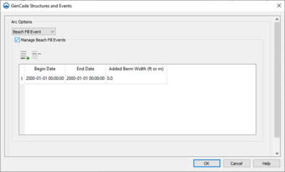
[[File:Structure_Beachfill.png|alt=GenCade Structures dialog showing the Beach Fill event option|thumb|400x400px|''GenCade Structures'' dialog showing the ''Beach Fill event'' option]] | |||
Beach fills may be created either seaward or landward of the shoreline. If there are many beach fills in one location during the simulation, draw the beach fills carefully so that the arcs do not connect or intersect. | |||
For this type in the dialog, a table of columns appears once the "Manage Beach Fill Events" option is selected. The available column values are: | |||
*'''Begin Date''' | |||
*'''End Date''' | |||
*'''Added Berm Width''' (ft or m) | |||
=Other= | =Other= | ||
These types will have more information added soon. | |||
==SBAS Polygon== | ==SBAS Polygon== | ||
==SBAS Flux== | ==SBAS Flux== | ||
| Line 81: | Line 148: | ||
<references /> | <references /> | ||
[[Category:GenCade Dialogs|S]] | [[Category:GenCade 2.0 Dialogs|S]] | ||
[[Category:GenCade|S]] | [[Category:GenCade|S]] | ||
Revision as of 15:24, 28 March 2024
The GenCade Structures/Events coverage allows the user to define the structures and planned events for a GenCade simulation. Only one of this type coverage can be added to the simulation, so it should contain arcs for all structures and events needed. However, there can be multiple arcs of the same types within this coverage unless it is mentioned in the sections below.
This coverage uses Feature Arcs within the SMS to define the positioning for each type and to assign a variety of attributes including:
- Geometric objects – shoreline and contours.
- Structures – jetty, inlet, seawall, or breakwater and their associated parameters.
- Events – bypass or beach nourishment events and their time ranges and parameters.
Add GenCade Structures Coverage
This coverage is added to SMS by right-clicking on the "Map Data" icon in the data tree and selecting New Coverage, then Models and then GenCade Beta. Inside the GenCade Beta item, there are three options: GenCade Grid, GenCade Structures-Events, and GenCade Point Attributes. For the Structures coverage, select the GenCade Structures-Events option.
Note:
- Until this new interface fully replaces the old interface, there will be the older (GenCade) and newer (GenCade Beta) options in the coverage list.
This coverage is combined with the GenCade Grid and Points coverages to define all necessary pieces for the GenCade simulation. The Structures and Events coverage contains many different types as shown and described below.
Generic Arc
A Generic arc is the default for this dialog. Generic arcs are not yet assigned to be of any type and no information for these arcs is written to the input files.
Geometric Objects
Initial Shoreline
Only one Initial Shoreline is allowed per GenCade simulation. This is the definition of where the water meets the land. The points for the shoreline can be loaded into SMS in several ways including from ArcGIS Shapefiles. As mentioned in the USACE Technical Report[1],
Rigorous quality control is required to make sure the initial shoreline accurately represents the shoreline of interest. This process requires a detailed inspection of the shoreline. It is recommended to smooth out sudden changes in shoreline orientation especially near an inlet. The smoothing algorithm [in SMS] can be used for this purpose.
Regional Contour
In some cases, a regional contour may be added to the simulation. This arc can be defined in a similar manner, however it should be declared as the "Regional Contour" type under Arc Options on this dialog. Once the regional contour is specified, GenCade will maintain a desired overall shoreline curvature, e.g., preserving a bay shape without the presence of structures, even if the model is run for very long time periods.
Adding a regional contour represents a simplified method to describe the effects on the shoreline evolution of processes acting at longer time scales than what is simulated in GenCade. Thus, the regional contour should incorporate large-scale trends in shoreline shape, and not small-scale features that are expected to change at time scales modeled by GenCade.
Reference Line
If the user wishes to see another shoreline within the SMS interface, they can add one or more shorelines as the "Reference Line" type. This type is not written to any input file and is not used by GenCade in any way. It is merely for the user to reference within the SMS display window.
Structures
GenCade simulates the effects of common coastal structures on the shoreline position. Common types structures that can be represented are groins, jetties, harbor breakwaters (with respect to their functioning as a jetty or groin), detached breakwaters, seawalls, and "soft structures" such as beach fills. Considerable flexibility is allowed in combining these basic structures to produce more complex configurations, e.g., T-shaped groins, Y-shaped and half-Y groins, and jetties with spurs. Combinations of these types of structures are also possible.
Restrictions
There may be as many structures as needed for a GenCade simulation, however there are a few restrictions.
- Groins/jetties must be placed at least two grid cells apart.
- A groin/jetty may not be placed in the cell adjacent to a boundary cells, regardless if the boundary is gated by a groin or jetty or if it is an open beach.
- Diffracting structures of any type cannot overlap, except having their tips at the same cell wall.
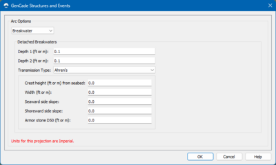
Breakwater
Detached breakwaters have a few options to define for each structure.
- Depth 1 (depth of the cell nearest the grid origin)
- Depth 2 (depth of the cell farthest from the grid origin)
- Transmission Type - selection from this combo box defines other parameters used in breakwater computations.
- Constant - single constant transmission coefficient.
- Ahren's - first of three formulations taking several additional coefficients.
- Seabrook & Hall - second formulation
- d'Angremond - third formulation
Note: All of these formulations take 5 parameters, and the first four are the same for each case.
- Freeboard to MSL
- Width
- Seaward side slope
- Shoreward side slope
The Ahren's and Seabrook & Hall formulations each take a fifth parameter for Armor stone D50.
The d'Angremond formulation takes a fifth parameter for Permeability.
Tip:
- For detailed analysis, it is recommended that at least nine grid points (eight cells) be placed behind detached breakwaters.
- For general analysis, a minimum of four cells is recommended.
Seawall
Effective sections of seawalls may be defined anywhere on the grid. It is noted that the seawall does not need to be straight, but may form a "curve" to follow the trend of the beach contours. The seawall may be placed at the shoreline or behind it. However, a seawall cannot be placed seaward of the shoreline.
- The Seawall option for this dialog has no parameters associated with it.
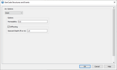
Groin
The Groin option takes a few parameters:
- Permeability
- Diffracting (check box)
- Seaward Depth (if Diffracting is checked).
Tip:
- For detailed analysis, it is recommended that at least nine grid points (eight cells) be placed between adjacent groins.
- For general analysis, a minimum of four cells is recommended.
Jetty (Left and Right)
The Left Jetty on Inlet and Right Jetty on Inlet options take a few parameters and is treated very similar to groins:
- Permeability
- Diffracting (check box)
- Seaward Depth (if Diffracting is checked).
The dialog for jetties is exactly the same as for Groins, see the figure for that example for reference.
Inlet
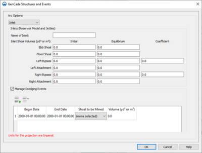
The inlet name, shoal volumes, dredging events, and bypassing coefficients are all defined when an inlet type is created.
The Inlets screen on this dialog has the following options:
- Name of Inlet
- Inlet Shoal Volumes
- Ebb Shoal - Initial and Equilibrium volumes
- Flood Shoal - Initial and Equilibrium volumes
- Left Bypass - Initial and Equilibrium volumes AND a bypass Coefficient
- Left Attachment - Initial and Equilibrium volumes
- Right Bypass - Initial and Equilibrium volumes AND a bypass Coefficient
- Right Attachment - Initial and Equilibrium volumes
- Manage Dredging Events - If this option is enabled (checked), a table consisting of numerous rows with a few columns appears.
- Begin Date
- End Date
- Shoal to be Mined
- Volume (to be mined).
Note: It is important to note that bypassing for each inlet defaults to the one cell immediately adjacent to either side of the inlet. However, the size and location may be defined by creating an Attachment Bar on one or both sides of the inlet.
Attachment Bar
The attachment bar option defines where bypassing to the left or right from an inlet will be bypassed to.
- The Attachment Bar option for this dialog has no parameters associated with it.
Events
Bypass Event
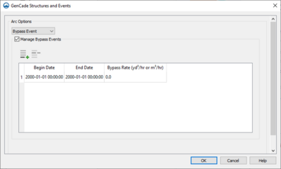
Bypass events act as a source and sink to the GenCade simulation. This event is treated differently than the bypassing that is associated with an Inlet. This type represents a physical bypass plant or operation where material is removed from one section of the grid and then placed onto another section of the grid.
For this type in the dialog, a table of columns appears once the "Manage Bypass Events" option is selected. The available column values are:
- Begin Date
- End Date
- Bypass Rate (yd3/hr or m3/hr)
Note: A positive value for the bypass rate will be interpreted as a source of sand and a negative value as a sink.
Beach Fill Event
Beach fills may be created either seaward or landward of the shoreline. If there are many beach fills in one location during the simulation, draw the beach fills carefully so that the arcs do not connect or intersect.
For this type in the dialog, a table of columns appears once the "Manage Beach Fill Events" option is selected. The available column values are:
- Begin Date
- End Date
- Added Berm Width (ft or m)
Other
These types will have more information added soon.
SBAS Polygon
SBAS Flux
References
- ↑ GenCade Version 1 Model Theory and User's Guide, https://hdl.handle.net/11681/7333
