GenCade 2.0 Grid Coverage


The GenCade Grid coverage allows the user to define the grid to be used by GenCade for all computations in a simulation. This coverage uses Feature Points within the SMS to define the positioning for each type and to assign the attributes:
Notes:
- Only one of this type coverage can be added to the simulation.
- Only one Begin and End point can be created in this coverage.
- As many Refine points can be added as needed to adequately represent all structures and events for the simulation.
Add GenCade Grid Coverage
This coverage is added to SMS by right-clicking on the "Map Data" icon in the data tree and selecting New Coverage, then Models and then GenCade Beta. Inside the GenCade Beta item, there are three options: GenCade Grid, GenCade Structures-Events, and GenCade Point Attributes. For the Grid coverage, select GenCade Grid.
Note:
- Until this new interface fully replaces the old interface, there will be the older (GenCade) and newer (GenCade Beta) options in the coverage list.
This coverage is combined with the GenCade Structures/Events and Points coverages to define all necessary pieces for the GenCade simulation.
Grid Creation
First, the user should use create two points which will define the Begin and Ending points for the GenCade Grid.
See the GenCade_Grid_Point_Attributes dialog for instructions and important notes.
Grid Definition Options
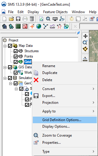
Next, the user should define the default grid cell size for this coverage. This is done by right clicking on the GenCade grid coverage in the SMS Data Tree and selecting "Grid Definitions Options" as shown Figure 2 on the right.
See the GenCade Grid Definition dialog for instructions and important notes.
Add Grid coverage to simulation
Once there is a Begin and End point defined and the default grid spacing has been set, the grid can be built by adding it to a GenCade simulation.
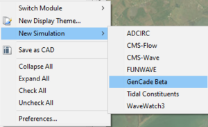
- Steps for creating a GenCade simulation can be found here.
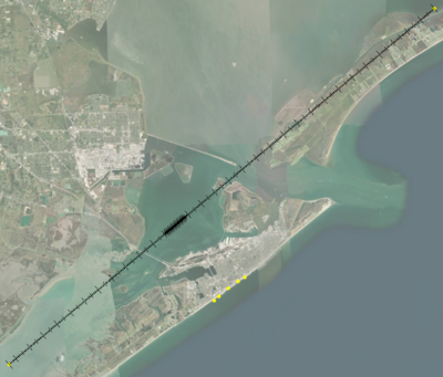
Once the grid has been added to the GenCade simulation, it will be generated and appear on the SMS Graphics Window (Figure 3).