GenCade 2.0 Point Dialog: Difference between revisions
mNo edit summary |
mNo edit summary |
||
| (15 intermediate revisions by the same user not shown) | |||
| Line 1: | Line 1: | ||
{{DISPLAYTITLE:GenCade 2.0 Point Coverage}} | {{DISPLAYTITLE:GenCade 2.0 Point Coverage}} | ||
{{TOC right}} | {{TOC right}} | ||
The GenCade Point coverage allows the user to define specific points in the interface used by GenCade. This coverage uses Feature Points within the SMS to define the positioning for each type and to assign the attributes: | The GenCade Point coverage allows the user to define specific points in the interface used by GenCade. This coverage uses Feature Points within the SMS to define the positioning for each type and to assign the attributes. There are three types of functionality that can assigned to a point: | ||
*Attribute Modification | |||
*Wave Gage | |||
* Tidal Current Gage | |||
'''Notes:''' | '''Notes:''' | ||
*Only one of this type coverage can be added to the simulation. | *Only one of this type coverage can be added to the simulation. | ||
*Only one functionality type is available for each point. For example, this means the same point cannot be used for both a Wave gage and an Attribute Modification point. | |||
This coverage is | == Add GenCade Point Coverage == | ||
This coverage is added to SMS by right-clicking on the "Map Data" icon in the data tree and selecting <u>New Coverage</u>, then <u>Models</u> and then <u>GenCade Beta</u>. Inside the GenCade Beta item, there are three options: ''GenCade Grid'', ''GenCade Structures-Events'', and ''GenCade Point Attributes''. For the Point coverage, select the <u>GenCade Point Attributes</u> option. | |||
'''Note:''' | |||
* Until this new interface fully replaces the old interface, there will be the older (GenCade) and newer (GenCade Beta) options in the coverage list. | |||
[[Category:GenCade| | This coverage is combined with the GenCade <u>[[GenCade 2.0 Structures Dialog|Structures/Events]]</u> and <u>[[GenCade 2.0 Grid Coverage|Grid]]</u> coverages to define all necessary pieces for the GenCade simulation. | ||
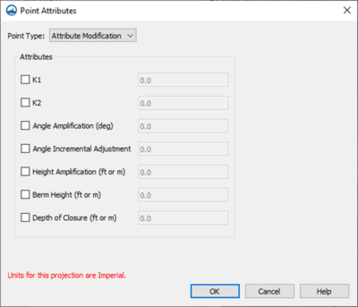
[[File:Point_Mod.png|thumb|400px|alt=Figure 1. Display of Point Attribute screen for Attribute Modification points.|Figure 1. Display of Point Attribute screen for Attribute Modification points.]] | |||
=Attribute Modification= | |||
This type of point will modify from the existing default values for all cells leading up to the point location. | |||
For example, in the GenCade Model Control, the default values for K1 and K2 have been set to 0.4 and 0.25, respectively. If the user wanted to use different values for these parameters in specific parts of the grid, they can use Attribute Modification points to accomplish it. | |||
The seven parameters which can have "modification" values set are: | |||
*'''K1''' | |||
*'''K2''' | |||
*'''Angle Amplification''' | |||
*'''Angle Incremental Adjustment''' | |||
*'''Height Amplification''' | |||
*'''Berm Height''' | |||
*'''Depth of Closure''' | |||
Any one or more of these parameters may be set for each point of this type. An example of this dialog screen is shown in Figure 1. | |||
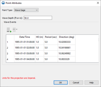
[[File:Point_Wave.png|thumb|400px|alt=Figure 2. Display of Point Attribute screen for Wave gages.|Figure 2. Display of Point Attribute screen for Wave gages.]] | |||
=Wave Gage= | |||
This type of point will allow the user to designate the point as being a wave gage and to attach a series of times and wave parameters to be used in the simulation. | |||
For this type, the user is able to define the '''Wave Gage depth''' as well as other wave parameters for a range of dates and times. | |||
The table contains the following columns for each row: | |||
*'''Date/Time''' | |||
*'''H0''' – The wave height (m) | |||
*'''Period''' – The significant wave period (seconds). | |||
*'''Direction''' – the mean wave direction (degrees). | |||
An example of this dialog screen is shown in Figure 2 | |||
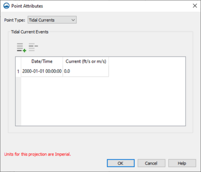
[[File:Point_Tide.png|thumb|400px|alt=Figure 3. Display of Point Attribute screen for Tidal Current gages.|Figure 3. Display of Point Attribute screen for Tidal Current gages.]] | |||
=Tidal Current Gage= | |||
This type of point will allow the user to designate this point as being a tidal current gage and to attach a series of times and current speeds to be used in the simulation. | |||
For this type, the user is able to define the tidal parameters for a range of dates and times. | |||
The table contains the following columns for each row: | |||
* '''Date/Time''' | |||
* '''Current (ft/s or m/s)''' | |||
An example of this dialog screen is shown in Figure 3. | |||
[[Category:GenCade 2.0 Dialogs|P]] | |||
[[Category:GenCade|P]] | |||
Latest revision as of 20:25, 3 December 2024
The GenCade Point coverage allows the user to define specific points in the interface used by GenCade. This coverage uses Feature Points within the SMS to define the positioning for each type and to assign the attributes. There are three types of functionality that can assigned to a point:
- Attribute Modification
- Wave Gage
- Tidal Current Gage
Notes:
- Only one of this type coverage can be added to the simulation.
- Only one functionality type is available for each point. For example, this means the same point cannot be used for both a Wave gage and an Attribute Modification point.
Add GenCade Point Coverage
This coverage is added to SMS by right-clicking on the "Map Data" icon in the data tree and selecting New Coverage, then Models and then GenCade Beta. Inside the GenCade Beta item, there are three options: GenCade Grid, GenCade Structures-Events, and GenCade Point Attributes. For the Point coverage, select the GenCade Point Attributes option.
Note:
- Until this new interface fully replaces the old interface, there will be the older (GenCade) and newer (GenCade Beta) options in the coverage list.
This coverage is combined with the GenCade Structures/Events and Grid coverages to define all necessary pieces for the GenCade simulation.

Attribute Modification
This type of point will modify from the existing default values for all cells leading up to the point location.
For example, in the GenCade Model Control, the default values for K1 and K2 have been set to 0.4 and 0.25, respectively. If the user wanted to use different values for these parameters in specific parts of the grid, they can use Attribute Modification points to accomplish it.
The seven parameters which can have "modification" values set are:
- K1
- K2
- Angle Amplification
- Angle Incremental Adjustment
- Height Amplification
- Berm Height
- Depth of Closure
Any one or more of these parameters may be set for each point of this type. An example of this dialog screen is shown in Figure 1.

Wave Gage
This type of point will allow the user to designate the point as being a wave gage and to attach a series of times and wave parameters to be used in the simulation.
For this type, the user is able to define the Wave Gage depth as well as other wave parameters for a range of dates and times.
The table contains the following columns for each row:
- Date/Time
- H0 – The wave height (m)
- Period – The significant wave period (seconds).
- Direction – the mean wave direction (degrees).
An example of this dialog screen is shown in Figure 2

Tidal Current Gage
This type of point will allow the user to designate this point as being a tidal current gage and to attach a series of times and current speeds to be used in the simulation.
For this type, the user is able to define the tidal parameters for a range of dates and times.
The table contains the following columns for each row:
- Date/Time
- Current (ft/s or m/s)
An example of this dialog screen is shown in Figure 3.