GenCade Boundary Conditions: Difference between revisions
| Line 17: | Line 17: | ||
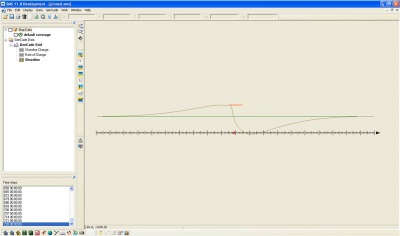
Figure 4 shows the modeled shoreline after a two year simulation. Since both boundaries are pinned, the shoreline at the extents of the grid does not change. Since the grid is only 5000 ft long, it is possible that shoreline change should occur at the extents of the grid. Therefore, for this case, a larger grid may be necessary. | Figure 4 shows the modeled shoreline after a two year simulation. Since both boundaries are pinned, the shoreline at the extents of the grid does not change. Since the grid is only 5000 ft long, it is possible that shoreline change should occur at the extents of the grid. Therefore, for this case, a larger grid may be necessary. | ||
[[Image:simpinned.jpg|400px|thumb|left|Figure 4. Shoreline Change with Pinned Boundaries]] | |||
<br style="clear:both" /> | |||
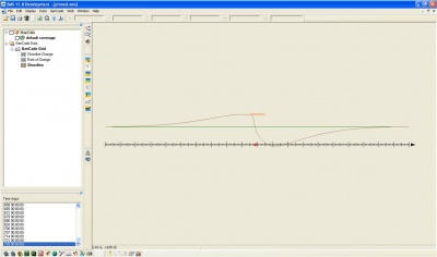
[[Image:sim_pinned.jpg|400px|thumb|left|Figure 4. Shoreline Change with Pinned Boundaries]] | [[Image:sim_pinned.jpg|400px|thumb|left|Figure 4. Shoreline Change with Pinned Boundaries]] | ||
<br style="clear:both" /> | <br style="clear:both" /> | ||
Revision as of 15:42, 5 November 2010
Boundary Conditions in GenCade
The lateral boundary condition information is included in the GenCade Model Control window under the GenCade menu. GenCade presently has three options for boundary conditions: pinned, moving, and gated. A boundary specified as pinned means that boundary will not move from the initial shoreline position. This is also the default boundary condition. If a moving boundary condition is selected, the boundary will a specified distance over a certain time period (specified by the user). A gated boundary condition is bounded with a groin.
Pinned
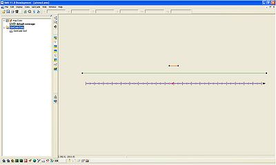
If the lateral boundary conditions (Lateral BC tab) are not changed, the defaulted pinned boundary condition will be used. A simple example is shown below. In this simple case, there is a straight shoreline with one breakwater at the center of the grid. The waves are idealized (H = 0.5 m, T = 6 s, wave direction = 30 degrees), and the simulation is run for two years. Figure 1 shows the setup in GenCade. After selecting Model Control in the GenCade menu, the GenCade Model Control window will open. The last tab under GenCade Model Control is Lateral BC. When the pinned boundary condition is selected, all of the other options in the tab are grayed out.
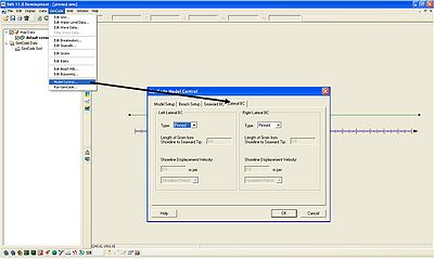
The boundary conditions are specified in the *.gen file under the heading "BEACH." LBCTYPE refers to the left boundary condition while RBCTYPE refers to the right boundary condition. For the pinned boundary condition, LBCTYPE and RBCTYPE will be 0. Since all of the other options in the Lateral BC window were grayed out, all of the other variables related to boundary conditions in the *.gen file will also be zero.
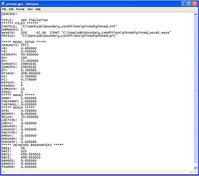
Figure 4 shows the modeled shoreline after a two year simulation. Since both boundaries are pinned, the shoreline at the extents of the grid does not change. Since the grid is only 5000 ft long, it is possible that shoreline change should occur at the extents of the grid. Therefore, for this case, a larger grid may be necessary.
