Channel infilling under steady currents: Difference between revisions
No edit summary |
|||
| Line 1: | Line 1: | ||
== '''Setup''' == | == '''Setup''' == | ||
The experiment consist of a trapezoidal channel of uniform find sand (d50 = 0.16 mm) with a steady flow (0.51 m/sec) perpendicular to the channel axis (Gallappatti and Vreugdenhil 1985). The water depth on the upstream bank is about 0.39 m. Three bank slopes were tested: 1:3, 1:7, and 1:10. A flux boundary condition was used at the inlet and a water level boundary condition at the outlet. A constant Manning n coefficient of 0.025 (default) was used. The Lund-CIRP transport formula was used for all three test cases. The morphologic scaling factor was set to 1.0. The adaptation length was calibrated to be 0.6 m. | The experiment consist of a trapezoidal channel of uniform find sand (d50 = 0.16 mm) with a steady flow (0.51 m/sec) perpendicular to the channel axis (Gallappatti and Vreugdenhil 1985). The water depth on the upstream bank is about 0.39 m. Three bank slopes were tested: 1:3, 1:7, and 1:10. A flux boundary condition was used at the inlet and a water level boundary condition at the outlet. A constant Manning n coefficient of 0.025 (default) was used. The Lund-CIRP transport formula was used for all three test cases. The morphologic scaling factor was set to 1.0. The adaptation length was calibrated to be 0.6 m. | ||
Latest revision as of 13:38, 13 October 2010
Setup
The experiment consist of a trapezoidal channel of uniform find sand (d50 = 0.16 mm) with a steady flow (0.51 m/sec) perpendicular to the channel axis (Gallappatti and Vreugdenhil 1985). The water depth on the upstream bank is about 0.39 m. Three bank slopes were tested: 1:3, 1:7, and 1:10. A flux boundary condition was used at the inlet and a water level boundary condition at the outlet. A constant Manning n coefficient of 0.025 (default) was used. The Lund-CIRP transport formula was used for all three test cases. The morphologic scaling factor was set to 1.0. The adaptation length was calibrated to be 0.6 m.

Results
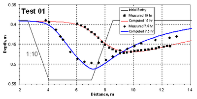
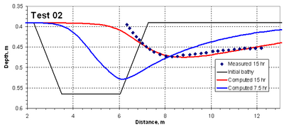
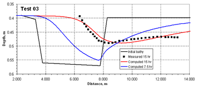
The figures below show a comparison between measured and computed bed elevations.


References
Gallappatti, G., and Vreugdenhil, C.B. (1985). "A depth-integrated model for suspended sediment transport". J. Hydr. Res., 23(4), 359-377.