GenCade:Structures: Difference between revisions
m (Added sections) |
|||
| Line 70: | Line 70: | ||
==Impact of Detached Breakwaters == | ==Impact of Detached Breakwaters == | ||
The response of the shoreline to placement of a detached breakwater (DBW) must be considered in the design process. The transmission coefficient is a leading parameter in controlling beach response to DBWs (Hanson and Kraus 1990). GENESIS (Hanson and Kraus 1989) was applied to model shoreline change both in the field and in movable-bed physical model experiments based on its capability of representing combined wave diffraction, refraction, and transmission at multiple DBWs (e.g., Hanson and Kraus 1989, 1990, 1991a, 1991b; Hanson et al. 1989; Rosati et al. 1992; Gravens and Rosati 1994; Herbich et al. 1996). Initially, the GENESIS model only represented a constant transmission coefficient (K_t) for DBWs. To describe wave transmission in the modeling system, a value of a transmission coefficient K_t was provided for each DBW as an input parameter. The transmission coefficient, defined as the ratio of the height of the incident waves directly shoreward of the breakwater to the | |||
height directly seaward of the breakwater, has the range <math> | |||
== Useful Links == | == Useful Links == | ||
Revision as of 16:30, 3 March 2023
Types of Structures
GenCade simulates the effects of common coastal structures on the shoreline position. Generic types of structures that can be represented are groins, jetties, harbor breakwaters (with respect to their functioning as a jetty or groin), detached breakwaters, seawalls, and the “soft structure” or beach fill. Considerable flexibility is allowed in combining these basic structures to produce more complex configurations, e.g., T-shaped groins, Y-shaped and half-Y groins, and jetties with spurs. Combinations of these types of structures are also possible.
In shoreline change modeling, structures exert two direct effects:
- Structures that extend into the surf zone block a portion or all of the sand moving alongshore on their updrift sides and reduce the sand supply on their downdrift sides. These structures, referred to as ‘non- diffracting’ groins or jetties, only affect the sediment transport through direct blocking and have no effect on the waves.
- Groins/jetties with seaward ends extending well beyond the surf zone, referred to as ‘diffracting groins/jetties’, and detached breakwaters, produce wave diffraction. This causes the local wave height and direction to change, altering the longshore sand transport rate. In addition to this, the diffracting groins and jetties also block the sediment transport directly.
In reality, all groins and jetties are ‘diffracting’ to some degree. As diffracting structures require substantial computational effort, the user has been given the option to classify short groins and jetties as being ‘non- diffracting’, to save computational time. It is up to the user to determine for which groins and jetties wave diffraction may be ignored. Preferably, comparative simulations should be run, where short groins and jetties are represented as ‘diffracting’ and ‘non-diffracting’, respectively. Comparisons of simulation results may indicate the groins and jetties for which diffraction may be ignored. Only groins and jetties may be regarded as ‘non-diffracting’. Detached breakwaters are always regarded as diffracting as are groins and jetties that are combined with detached breakwaters or each other to form composite structures such as Y-groins.
Placement of groins, jetties,and detached breakwaters
This section describes capabilities and limitations in placing structures in GenCade. Idealized examples of plan views of various configurations are given for reference. It is noted that structures are represented as infinitesimally thin objects in the model. For example, a groin or jetty is located at the wall of a single cell and cannot occupy the position of more than one wall. In the figures below, structures are drawn thick for visibility only.
Three basic rules governing placement of groins, jetties, and detached breakwaters are:
- The position of a structure is defined by the location of its tip(s), and
these positions are located at cell walls;
- There must be at least two cells between groins and jetties. As an
important special case, a groin cannot be placed in the cell next to a lateral boundary;
- The locations of the tips of diffracting structures can coincide (be
located at the same cell wall), but they cannot overlap.
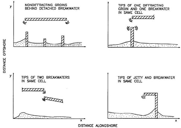
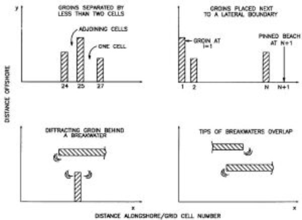
Figures 1 and 2 give schematic examples of structure placements in GenCade. Structures that affect the waves (detached breakwaters and diffracting groins and jetties) are denoted as ‘diffracting structures’ and indicated by a ‘)))’ symbol in the figures.
Figure 1 gives examples of allowable Non- diffracting groins/jetties may be placed behind a diffracting breakwater (but diffracting groins/jetties cannot) (upper left sketch). The other three sketches in this figure show situations involving the tips of two structures sharing the same grid cell. The tip of a detached breakwater and a diffracting groin/jetty can be at the same longshore grid cell, as can the tips of two detached breakwaters. Two or three diffracting tips may be put together to form an angled structure such as a spur groin/jetty (lower right sketch), Y-groin, angled groin, etc. In such a case, the attaching points must be located in the same cell, at the same distance offshore, and having the same depth (see text below).
Figure 2 illustrates the major restrictions on placement of structures. Groins/jetties must be placed at least two grid cells apart (upper left sketch). This is not a serious limitation, since groins in the field are typically placed one to two groin lengths apart. A groin/jetty cannot be placed in the cell adjacent to a boundary cell, whether the boundary is gated by a groin/jetty or being an open beach (upper right sketch). Diffracting structures of any type cannot overlap (lower left and lower right) (except having their tips at the same cell wall; Figure 1).
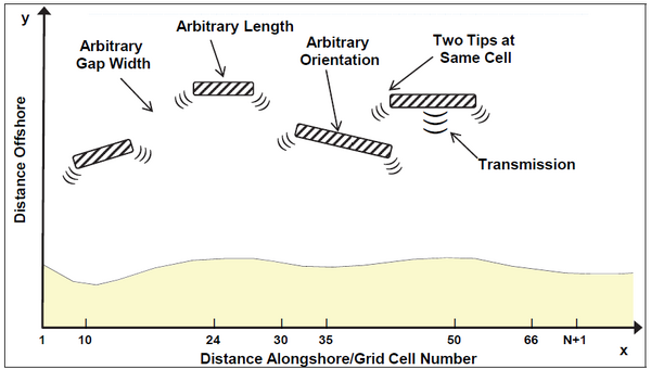
Figure 3 illustrates detached breakwater parameters that may be varied. Detached breakwaters are defined in the modeling system by specifying pairs of ends or tips of the structures. Wave transmission coefficients must also be given. As a summary, as long as detached breakwaters do not overlap (except for two tips sharing the same grid cell wall), the modeler is free to vary the length, transmission coefficient, orientation, distance offshore, and, in the case of segmented breakwaters, the gap width between structures.
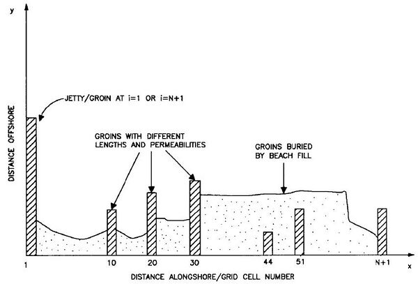
Figure 4 illustrates various representations of groins/jetties. Simple groins/jetties can have arbitrary lengths and are aligned parallel to the y- axis by GenCade; i.e., angled groins/jetties cannot be directly modeled. A groin/jetty cannot be flanked on its landward end; i.e., it cannot be isolated in the surf zone. However, groins/jetties can be covered by sand, as may occur during a beach fill, and will then be inactive. If uncovered by wave action, they will resume functioning.
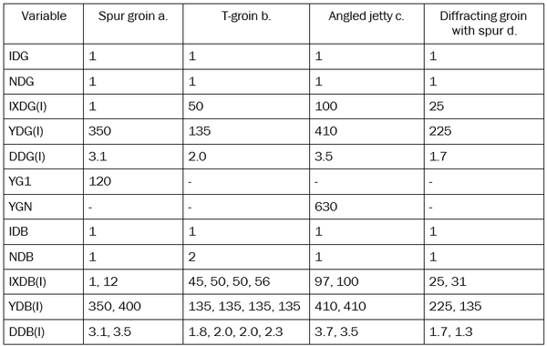
Complex groin or jetty configurations, such as Y-groins, T-groins, and spur jetties, can be represented by placing tips of diffracting groins and detached breakwaters together. Figure 5 shows examples of complex structure configurations that may be represented, and Table 1 shows the corresponding values defining these configurations.
Several features in the examples in Figure 5 deserve attention:
- At locations where structures are attached, they must be located in the same cell, at the same distance offshore, and having the same depth. If not, GenCade will not recognize the structures as being connected;
- The top of the “T” forming a T-groin (such as in example c) must be represented by two structures, each attaching to the diffracting groin. Otherwise, the configuration would be illegal (overlap of diffracting structures) as shown in Figure 2;
- The connection between two attaching detached breakwaters must be at the exact same point in all specifications (as in example b).
- All groins/jetties attaching to detached breakwaters must be represented as diffracting.
Impact of Groins and Jetties
In GenCade, two types of sand movement past a groin or jetty are simulated. One type of movement is around the seaward end of the structure, called bypassing, and the other is through and over the structure, called transmission. Bypassing is assumed to take place if the water depth at the tip of the structure DG is less than the depth of active longshore transport DLT (see Empirical Parameters). Since the shape of the bottom profile is known (see Empirical Parameters), DG is determined from knowledge of the distance between the tip of the structure and the location of the shoreline. However, because groins/jetties are located at grid cell walls between two calculated shoreline positions, this depth is not unique. In GenCade, the updrift depth is used. To represent sand bypassing, a bypassing factor BYP is introduced and defined as:
which is calculated at each time step.
Analogously, a permeability factor PERM is introduced to describe sand transmission over, through, and landward of a shore-connected structure such as a groin. A high (in relation to the mean water level), structurally tight groin that extends far landward so as to prevent landward sand bypassing is assigned PERM = 0, whereas a completely “transparent” structure is assigned the value PERM = 1. Values of PERM thus lie in the range of and must be specified through judgment of the modeler based upon, for example, the structural characteristics of the groin (jetty, breakwater), its elevation, the tidal range at the site, or an on- site inspection of the structure. Aerial photographs are often helpful in estimating a structure’s amount of void space (hence PERM) in relation to other structures on the model grid. The optimal value of PERM for each structure must then be determined in the process of model calibration.
With the values of BYP and PERM determined, GenCade calculates the total fraction F of sand passing over, around, or through a shore- connected structure as (Hanson 1987):
This fraction is calculated at every time step for each shore connected (groin-type) structure defined along the model grid.
Impact of Detached Breakwaters
The response of the shoreline to placement of a detached breakwater (DBW) must be considered in the design process. The transmission coefficient is a leading parameter in controlling beach response to DBWs (Hanson and Kraus 1990). GENESIS (Hanson and Kraus 1989) was applied to model shoreline change both in the field and in movable-bed physical model experiments based on its capability of representing combined wave diffraction, refraction, and transmission at multiple DBWs (e.g., Hanson and Kraus 1989, 1990, 1991a, 1991b; Hanson et al. 1989; Rosati et al. 1992; Gravens and Rosati 1994; Herbich et al. 1996). Initially, the GENESIS model only represented a constant transmission coefficient (K_t) for DBWs. To describe wave transmission in the modeling system, a value of a transmission coefficient K_t was provided for each DBW as an input parameter. The transmission coefficient, defined as the ratio of the height of the incident waves directly shoreward of the breakwater to the height directly seaward of the breakwater, has the range <math>
