GenCade Val:Benchmark Cases
A series of standardized test cases was developed to demonstrate isolated GenCade model capabilities and verify results against established legacy models (e.g., GENESIS). Simple idealized cases focusing on each of the primary model processes and coastal structures were evaluated separately.Isolation of individual modeled components is an effective means of examining the fundamental skill of a model and can be a practical tool for identifying potential errors, oversights, or omissions when investigating individual components of the model under simple idealized cases.
The standardized benchmark cases developed here are separated into the primary coastal structures and project components that are frequently applied in GenCade. Each of the cases is presented with a range in wave forcing to test symmetry of process calculation. GENESIS simulations were also developed following corresponding test cases to evaluate how GenCade results agree with the well-validated legacy model and to support user-confidence for the transfer and migration from GENESIS.
GenCade model setup
Model domain
Two categories of idealized model domains were developed for the standardized benchmark cases: straight shoreline domains and concave embayment domains. The purpose of the straight shoreline domains is to provide an uncomplicated foundation to test the most fundamental processes and the impact of coastal structures within the GenCade model. The purpose of the concave embayment domains is to examine the effects wave forcing and structures have on a continuous and uniform alongshore shoreline angle gradient and examine regional contour capabilities. Figures 1 through 7 show each of the seven domains in the straight shoreline category. Figure 1 represents the simplest case with a straight shoreline and no structures or project features within the domain. Figures 2 through 7 build upon this domain with the addition of individual coastal structures or project components. These structures or components include a single groin (Figure 2), a detached breakwater (Figure 3), a T-head groin (Figure 4), a seawall with a groin to force shoreline erosion to the seawall (Figure 5), a beach fill project (Figure 6), and an inlet with jetties (Figure 7).
Figures 8 and 9 show the two domains in the concave shoreline category. The concave shorelines were developed using a simple quadratic formula to maintain symmetry. The quadratic function employed for these concave shorelines was:
y = ax2
where a = 10-4. Figure 8 represents a simple case with a concave shoreline and no structures or project features within the domain. Figure 9 builds upon this domain with the addition of two groins.
- Idealized model domains
-
Figure 1. GenCade straight shoreline with no structures domain.
-
Figure 2. GenCade straight shoreline with single groin domain.
-
Figure 3. GenCade straight shoreline with detached breakwater domain.
-
Figure 4. GenCade straight shoreline with T-head groin domain.
-
Figure 5. GenCade straight shoreline with seawall domain.
-
Figure 6. GenCade straight shoreline with beachfill domain.
-
Figure 7. GenCade straight shoreline with structured inlet domain.
-
Figure 8. GenCade concave shoreline with no structures.
-
Figure 9. GenCade concave shoreline with two groins.
Model forcing: waves
Simulations of the standardized benchmark cases were conducted under various wave forcing. Constant wave forcing over the entire length of the simulation was initially examined for general investigation purposes. First constant waves with 0.75 m offshore wave height and 8 sec period were applied as forcing for both positive wave angles at +15-deg and negative wave angles at -15-deg. Wave forcing simulations were also conducted for constant zero-deg (i.e., shore normal) angles and simulations for all angles between +85-deg and -85-deg in 5-deg increments, but since the net shoreline change for these simulations results in zero change, they are not presented here. For all cases, wave inputs were supplied at the 50 m depth contour.
Model parameters
Wherever possible, the model parameters were held constant between each of the simulations in each domain category for purposes of consistency of comparison between simulations. Table 1 presents the model parameters common to all the standardized benchmark cases in the straight shoreline domains.
| Parameter | Value |
|---|---|
| DX, m | 10 |
| NX | 300 (Straight Domain); 360 (concave Domain) |
| DT, hr | 0.5 |
| K1 | 0.5 |
| K2 | 0.25 |
| ISMOOTH, # Cells in Smoothing Window | 3 |
| Non-Jetty boundary condition | Pinned |
GenCade model results and discussion
No structures
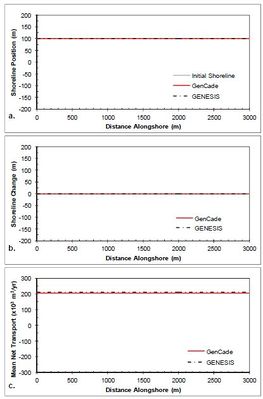
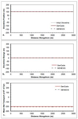
The simplest case of a straight shoreline without any coastal structures or coastal project components is presented first. Figure 10 shows the results after a 2-year simulation with constant +15-deg wave angle forcing. As one would expect, there is zero shoreline change since the alongshore gradients in transport are zero and transport is constant at approximately 200,000 m3/yr. Figure 11 shows the results after a 2-year simulation with constant -15-deg wave angle forcing. Similar to the positive wave angle forcing case, there is zero shoreline change since the alongshore gradients in transport are zero. Figure 11(c) indicates that transport is constant at approximately -200,000 m3/yr. Results for all simulations with no structures result in good agreement between GenCade results and GENESIS results.
- Figures 10-11
-
Figure 10. Calculated (a) shoreline position, (b) shoreline change, and (c) mean net transport for straight shoreline with no structures; H0 = 0.75 m, T = 8 sec, θ0 = +15-deg.
-
Figure 11. Calculated (a) shoreline position, (b) shoreline change, and (c) mean net transport for straight shoreline with no structures; H0 = 0.75 m, T = 8 sec, θ0 = -15-deg.
Single groin
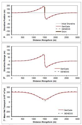
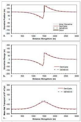
A case having a straight shoreline with a single groin 75 m long (175 m from the grid origin) at the center of the domain is presented next to examine shoreline response to the presence of a groin. Figure 12 shows the results after a 2-year simulation with constant +15-deg wave angle forcing. The groin presents an obstruction to longshore transport, which results in a reduction of transport rates as sediment is bypassed around the groin. This local transport reduction in the vicinity of the groin translates to a gradient in transport rates as transport transitions to and from background rates. This difference in sediment transport potential accounts for the accretion of sediment and resulting shoreline progradation seaward on the left (updrift) side of the groin as the transport rates decrease from 200,000 m3/yr to approximately 50,000 m3/yr at the groin. Conversely, as transport rates increase from 50,000 m3/yr in the vicinity of the groin back to 200,000 m3/yr outside of the region of groin influence, the expected downdrift shoreline erosion is observed. Figure 13 presents the results after a 2-year simulation with constant -15- deg wave angle forcing. The opposite pattern is observed in this example because transport is forced by negative wave angles relative to shore normal. Figure 13(c) shows that an increase in transport occurs on the left(downdrift) side of the groin from -200,000 m3/yr transport rate to -50,000 m3/yr in the vicinity of the groin. This positive gradient results in erosion while the negative gradient on the right (updrift) side of the groin results in accretion. Figures 12 and 13 clearly depict excellent agreement between GenCade results and GENESIS results for all simulations with a single groin as well as perfect symmetry between the positive and negative wave angle forcing.
- Figures 12-13
-
Figure 12. Calculated (a) shoreline position, (b) shoreline change, and (c) mean net transport for straight shoreline with single groin; H0 = 0.75 m, T = 8 sec, θ0 = +15-deg.
-
Figure 13. Calculated (a) shoreline position, (b) shoreline change, and (c) mean net transport for straight shoreline with single groin; H0 = 0.75 m, T = 8 sec, θ0 = -15-deg.
Detached breakwater
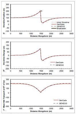
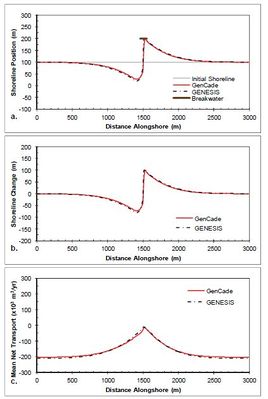
A detached breakwater case is evaluated in this section with a 90 m long emergent breakwater at the center of the domain located 100 m offshore of the shoreline at a depth of 6 m. Although this case is similar in configuration to the LSTF experiment detailed in section 3.1 of the GenCade Version 1 Model Theory and User's Guide Technical Report, this case is simulated at full prototype (i.e., larger) scale and over a much longer time frame. Figure 14 shows the results after a 2-year simulation with constant +15-deg wave angle forcing. These simulations result in a nearly symmetric shoreline change response in the lee of the breakwater and the development of a large salient approximately 75 m at the apex. The transport rates decrease from a background rate of 200,000 m3/yr to approximately 25,000 m3/yr directly behind the breakwater structure. Figure 15 presents the results after a 2-year simulation with constant -15-deg wave angle forcing. The opposite pattern is observed in this example because transport is forced by negative wave angles relative to shore normal. Figure 15(c) shows that an increase in transport occurs on the left(downdrift) side of the breakwater from -200,000 m3/yr background transport rate to -25,000 m3/yr in the lee of the breakwater. Again, the expected opposite shoreline response is observed here. Figures 14 and 15 show good overall agreement between GenCade results and GENESIS results. There is some difference observed between the results of the two models at the peaks of the salient and the downdrift erosional zones; however, this difference is small and accounts for only about two percent error (1.7 percent normalized mean absolute error and 2.3 percent normalized root-mean-square error). Differences between the GenCade and GENESIS results could be because of differences in the wave transformation model.
- Figures 14-15
-
Figure 14. Calculated (a) shoreline position, (b) shoreline change, and (c) mean net transport for straight shoreline with detached breakwater; H0 = 0.75 m, T = 8 sec, θ0 = +15-deg.
-
Figure 15. Calculated (a) shoreline position, (b) shoreline change, and (c) mean net transport for straight shoreline with detached breakwater; H0 = 0.75 m, T = 8 sec, θ0 = -15-deg.
T-groin
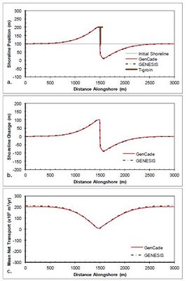
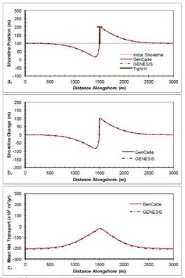
A T-groin case is demonstrated in this section with a 90 m long T-head groin at the center of the domain located 100 m offshore of the shoreline with all diffracting tips set to a depth of 6 m. Figure 16 shows the results after a 2-year simulation with constant +15-deg wave angle forcing. These simulations result in a nearly symmetric shoreline change response in the lee of the T-head and on either side of the groin and the accretion of shoreline out to the structure tip. The transport rates decrease from a background rate of 200,000 m3/yr to zero directly adjacent to the groin structure.Figure 17 presents the results after a 2-year simulation with constant -15-deg wave angle forcing. The opposite pattern is again observed in this example because transport is forced by negative wave angles relative to shore normal. Figure 17(c) shows that an increase in transport occurs on the left (downdrift) side of the groin from -200,000 m3/yr background transport rate to zero directly adjacent to the groin structure. Figures 16 and 17 show good agreement between GenCade results and GENESIS results over the entire length of the domain.
- Figures 16-17
-
Figure 16. Calculated (a) shoreline position, (b) shoreline change, and (c) mean net transport for straight shoreline with T-head groin; H0 = 0.75 m, T = 8 sec, θ0 = +15-deg.
-
Figure 17. Calculated (a) shoreline position, (b) shoreline change, and (c) mean net transport for straight shoreline with T-head groin; H0 = 0.75 m, T = 8 sec, θ0 = -15-deg.
Seawall
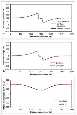
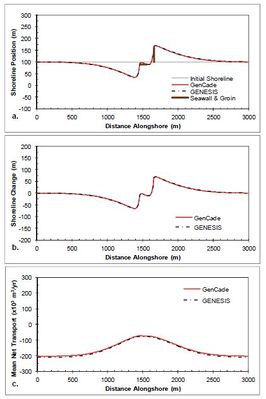
A seawall case is demonstrated next with a simple 100 m long seawall at the center of the domain located 10 m shoreward of (i.e., behind) the shoreline. Since a seawall that lies behind a straight shoreline with no other structures will never become exposed, a groin was added 100 m updrift of the seawall to force shoreline erosion in the vicinity of the seawall and expose the seawall to influence downdrift shoreline evolution. The groin follows the same dimensions of the single groin case. Figure 18 shows the results after a 2-year simulation with constant +15-deg wave angle forcing. The shoreline erodes to the right of the groin exposing the seawall. This halts erosion at the seawall, but accelerates erosion to the right (downdrift) of the seawall. Prior to the end of the simulation sediment accretes in front of the seawall resulting in the shoreline position observed in Figure 18(a).Figure 19 presents the results after a 2-year simulation with constant -15- deg wave angle forcing. In this case the groin was again placed updrift of the seawall, but since the wave angle is reversed, the groin is now 10 m to the right (updrift) of the seawall. Figures 46 and 47 again show excellent agreement between GenCade results and GENESIS results over the entire length of the domain.
- Figures 18-19
-
Figure 18. Calculated (a) shoreline position, (b) shoreline change, and (c) mean net transport for straight shoreline with seawall and groin; H0 = 0.75 m, T = 8 sec, θ0 = +15-deg.
-
Figure 19. Calculated (a) shoreline position, (b) shoreline change, and (c) mean net transport for straight shoreline with seawall and groin; H0 = 0.75 m, T = 8 sec, θ0 = -15-deg.
Beach fill
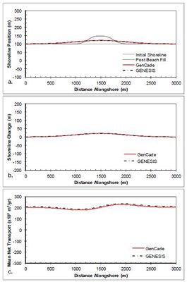
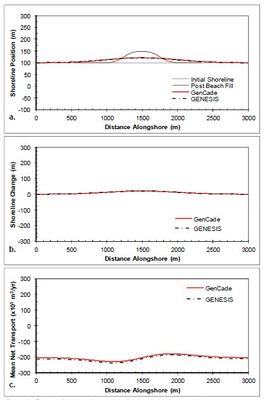
The simple case of a straight shoreline without any coastal structures is again presented in this section, but in this case a beach fill is added to evaluate shoreline progradation during the fill and the diffusion of the material and shoreline evolution after beach fill project completion. The beach fill project was initiated two months into the simulation and involved a construction duration of two months adding 50 m of berm width over an alongshore distance of 500 m. Upon beach fill completion (i.e., after two months of pumping fill onto the berm), no additional material was added. Figure 20 shows the results after a two-year simulation with constant +15-deg wave angle forcing. Figure 20(a) shows the shoreline position immediately after the fill project as well as the shoreline position after two years (i.e., 20-months after completion of the fill project). This clearly shows the lateral diffusion of the beach fill material along the shoreline. Figure 20(c) shows the transport gradient around the beach fill berm feature with the greatest deviation from background transport rate occurring at the fill transition zones. Figure 21 shows the results after a two-year simulation with constant -15-deg wave angle forcing. As one should expect, the shoreline evolution is identical to that shown in Figure 20 and only the transport rates are inverted. Results for all simulations with beach fills result in close agreement between GenCade results and GENESIS results.
- Figures 20-21
-
Figure 20. Calculated (a) shoreline position, (b) shoreline change, and (c) mean net transport for straight shoreline with a beach fill; H0 = 0.75 m, T = 8 sec, θ0 = +15-deg.
-
Figure 21. Calculated (a) shoreline position, (b) shoreline change, and (c) mean net transport for straight shoreline with a beach fill; H0 = 0.75 m, T = 8 sec, θ0 = -15-deg.
Inlet
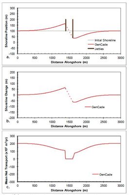
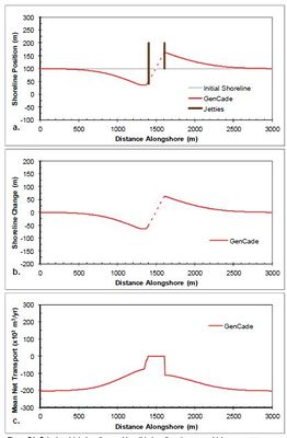
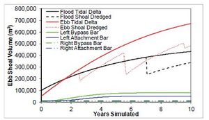
A case with a single inlet centered along a straight shoreline is demonstrated with GenCade in this section. The idealized inlet is 200 m wide and is stabilized with two 200 m jetties with bypassing coefficients set to 1.0, permeability set to 0.0, and diffracting tip depth set to 7 m. All morphological elements are set to equilibrium. The attachment bars spread bypassing across five cells (50 m) starting immediately adjacent to each of the jetties. Figure 22 shows the results after a two-year simulation with constant +15-deg wave angle forcing. This simulation results in an updrift offset inlet configuration that is typical of inlets associated with adequate updrift sediment supply and moderate transport rates. The development of an updrift fillet and downdrift erosion is observed in the shoreline response. The transport rates decrease from a background rate of 200,000 m3/yr to approximately 100,000 m3/yr adjacent to the jetty, then immediately drop to zero inside the inlet. Figure 23 shows the results after a two-year simulation with constant -15-deg wave angle forcing. The opposite pattern is observed in this example because transport is forced by negative wave angles relative to shore normal. Figure 23(c) shows that the transport rates increase from a background rate of -200,000 m3/yr to approximately -100,000 m3/yr adjacent to the jetty, then immediately rise to zero inside the inlet. Again,the expected opposite shoreline response is observed here. No comparison was developed for GENESIS because inlets, shoal evolution, and bypassing are new capabilities only incorporated in GenCade. Sediment transport and bypassing within the inlet are calculated within the inlet reservoir module of GenCade. Figure 24 shows the ebb and flood tidal delta evolution for these simulations compared to the shoal evolution in the same cases with 100,000 m3/yr after 2.5 years, 200,000 m3/yr after 5.5 years, and 50,000 m3/yr after 9.5 years dredged from the ebb shoal and with 150,000 m3/yr after seven years dredged from the flood shoal.
- Figures 22-24
-
Figure 22. Calculated (a) shoreline position, (b) shoreline change, and (c) mean net transport for straight shoreline with an inlet; H0 = 0.75 m, T = 8 sec, θ0 = +15-deg.
-
Figure 23. Calculated (a) shoreline position, (b) shoreline change, and (c) mean net transport for straight shoreline with an inlet; H0 = 0.75 m, T = 8 sec, θ0 = +15-deg.
-
Figure 24. Calculated ebb and flood shoal evolution.
Concave shoreline in GenCade – no structures
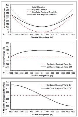
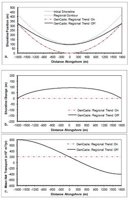
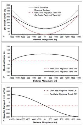
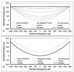
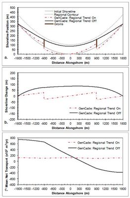
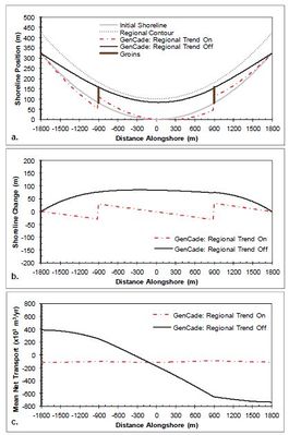
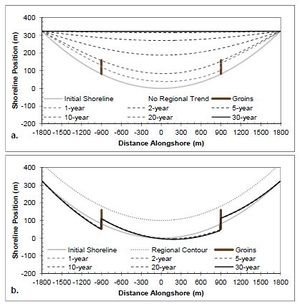
A case having a simple concave shoreline without any coastal structures or coastal project components is presented in this section to examine longterm shoreline response with and without the constraint of the regional equilibrium trend applied. Figures 25-27 show the results of calculated shoreline position, shoreline change, and net sediment transport after a two-year simulation of a concave shoreline case similar to the straight shoreline benchmark applications presented in Figures 10-23 for comparison of the effects of a cuspate regional trend on the solution. The results are presented with and without the application of the regional equilibrium contour for improved understanding of the consequences of the large-scale regional alongshore gradients have over the simulation. The wave transformation contour smoothing window (ISMOOTH) was set to the number of cells in the domain to maintain constant wave angle forcing. Figure 25 shows the results of a two-year regionally cuspate shoreline simulation with no structures forced by constant 0-deg. offshore wave angle. This figure demonstrates that the application of the regional trend forces the solution to maintain the regionally concave shape, while the results without the regional equilibrium contour begin to fill in and return to a straight shoreline due to the transport gradient across the domain. Figures 26 and 27 present similar results for +15-deg and -15-deg offshore wave angle, respectively. Figure 28 shows the shoreline position results after a 30-year simulation with constant -15-deg wave angle forcing. Because of the alongshore gradients in the shoreline orientation angle relative to the breaking wave angle, the concave shoreline progrades seaward and eventually fills the concave embayment completely resulting in a straight shoreline. In many cases this long-term shoreline straightening is not representative of the long-term equilibrium observations. In many cases the underlying geology or other coastal bathymetric or shoreline features result in a shoreline maintaining a long-term equilibrium regional shape over which local variations in shoreline evolution occur. For this reason, it is sometimes advantageous to employ the GenCade regional contour to maintain a longterm equilibrium shape. Figure 28 (b) presents a demonstration of this regional contour capability. This figure shows that when the regional contour is employed, the regional contour is maintained over the entire 30-year period.
- Figures 25-28
-
Figure 25. Calculated (a) shoreline position, (b) shoreline change, and (c) mean net transport for concave shoreline with no structures; H0 = 0.75 m, T = 8 sec, θ0 = 0-deg.
-
Figure 26. Calculated (a) shoreline position, (b) shoreline change, and (c) mean net transport for concave shoreline with no structures; H0 = 0.75 m, T = 8 sec, θ0 = +15-deg.
-
Figure 27. Calculated (a) shoreline position, (b) shoreline change, and (c) mean net transport for concave shoreline with no structures; H0 = 0.75 m, T = 8 sec, θ0 = -15-deg.
-
Figure 28. Calculated shoreline position (a) without regional contour and (b) with regional contour for concave shoreline no structures; H0 = 0.75 m, T = 8 sec, θ0 = -15-deg.
Concave shoreline in GenCade – two groins
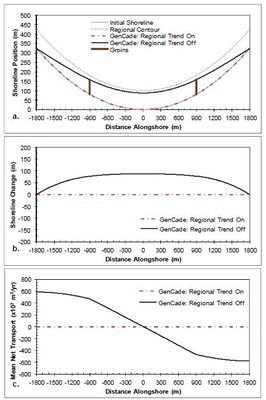
A case having a simple concave shoreline with one groin on each side of the domain is presented in Figures 29-32 to examine long-term shoreline response with and without the regional equilibrium contour applied and the local shoreline response to structures with opposing transport directions due to the shoreline angle gradient relative to the breaking wave angles. Figures 29-31 present results similar to Figures 25-28 but with local shoreline changes around structures imposed upon the regional trend during oblique wave forcing (Figures 30 and 31).Figure 32 shows the shoreline position results after a 30-year simulation with constant -15-deg. wave angle forcing. Because of the alongshore gradients in the shoreline orientation angle relative to the breaking wave angle, the local updrift fillet develops on one side of each groin. A similar pattern to what is observed in Figure 28 is also observed in Figure 32 when comparing results of the simulations with and without the application of the regional equilibrium contour.
- Figures 29-32
-
Figure 29. Calculated (a) shoreline position, (b) shoreline change, and (c) mean net transport for concave shoreline with two groins; H0 = 0.75 m, T = 8 sec, θ0 = 0-deg.
-
Figure 30. Calculated (a) shoreline position, (b) shoreline change, and (c) mean net transport for concave shoreline with two groins; H0 = 0.75 m, T = 8 sec, θ0 = +15-deg.
-
Figure 31. Calculated (a) shoreline position, (b) shoreline change, and (c) mean net transport for concave shoreline with two groins; H0 = 0.75 m, T = 8 sec, θ0 = -15-deg.
-
Figure 32. Calculated shoreline position (a) without regional contour and (b) with regional contour for concave shoreline with two groins; H0 = 0.75 m, T = 8 sec, θ0 = -15-deg.
Wave breaking sensitivity
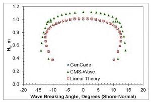
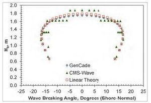
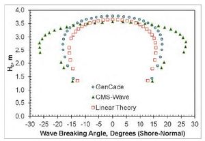
A series of GenCade simulations were executed to evaluate the sensitivity to breaking wave parameters of the GenCade internal wave model. Calculations were verified against linear wave theoretical estimates and results from CMS-Wave (Lin et al. 2008) simulations. The simplest case of a straight shoreline without any coastal structures or coastal project components (refer to section 3.2.2.1 of the GenCade Technical Report) was employed for this application. Offshore wave forcing was applied at a depth of 50 m and for all angles between +85-deg and -85-deg at 5-deg increments. Simulations were executed for three wave height and period combinations: 1) H0 = 0.75 m and Tp = 8 sec; 2) H0 = 1.50 m and Tp = 8 sec; and 3) H0 = 3.00 m and Tp =12 sec. A corresponding CMS-Wave model application was developed employing a grid 3.2 km in the cross-shore direction by 3.6 km wide in the alongshore direction with 5-m cell resolution (i.e., 640 x 720 = 460,800 cells). The bathymetric data was developed to represent an idealized equilibrium profile based on a medium sand median grain size of d50 = 0.25 mm (i.e., Dean A-parameter = 0.11139). Wave energy was supplied at the offshore boundary (depth = 50 m) as a TMA-type unidirectional spectrum for each wave condition consisting of 11 frequency bins (0.05 to 0.15 Hz at 0.01-Hz increment) and 35 direction bins (covering a half-plane with 5-deg spacing). Although CMS-Wave is a spectral phase-averaging wave model, breaking wave parameters were estimated by selecting the peak significant wave height output immediately offshore of the breaking wave index output flag. Figures 33-35 present the results for each wave condition comparing breaking wave parameters for GenCade, CMS-Wave, and a third linear wave theoretical estimate method based on a planar beach with slope 1.5:100 (m = 0.015). GenCade results agree well with the linear theory with only slightly larger waves calculated by GenCade for the high energy case (H0 = 3.00 m and Tp =12 sec). GenCade calculated breaking wave height results agree well with CMS-Wave calculated Hb results with an average root-mean-square error (RMSE) of 2 cm. Breaking wave directions do not agree quite as well, with an average RMSE of 2.2-deg, but the majority of the error is accounted for in the acutely oblique angles of the storm condition (H0 = 3 m; Tp = 12 sec). Despite narrow spectrum input for CMS-Wave, directional spreading may account for much of the differences observed.
- Figures 33-35
-
Figure 33. Calculated breaking wave height and direction; H0 = 0.75 m, T = 8 sec, θ0 = -85-deg. through +85-deg. at 5-deg. intervals.
-
Figure 34. Calculated breaking wave height and direction; H0 = 1.50 m, T = 8 sec, θ0 = -85-deg. through +85-deg. at 5-deg. intervals.
-
Figure 35. Calculated breaking wave height and direction; H0 = 3.00 m, T = 12 sec, θ0 = -85-deg. through +85-deg. at 5-deg. intervals.
Reference: Lin, L., Z. Demirbilek, H. Mase, J. Zheng, and F. Yamada. 2008. CMS-Wave: A Nearshore Spectral Wave Processes Model for Coastal Inlets and Navigations Projects. ERDC/CHL-TR-08-13, US Army Engineer Research and Development Center, Coastal and Hydraulics Laboratory, Vicksburg, MS.


