Quick Response Toolbox: Step 2 - Generate Transect and Clip Mask

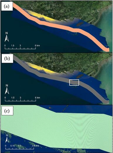
Summary: This step takes transects and the split baseline from Step 1 to create polygon features called the transect mask and clip mask. The clip mask is a rectilinear polygon feature that covers the whole study area and defined by the baseline and transect length. The transect mask is multiple polygon features that split the clip mask into equally sized sections or “bins” based on transect spacing. In subsequent steps, volume change will be calculated in each bin separately.
Transects: The transects generated previously that extend from the baseline to the depth of closure. This step honors selection of the transects in the case that only certain transects need points generated.
Split Baseline: The version of the previously created baseline that has been split at each point where the transects intersect.
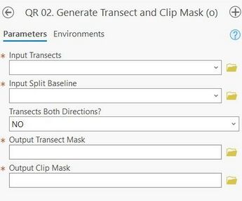
Transects Both Directions?: Indication to the toolbox if the transects created in step 1 are on only one side of the baseline (left or right) or both.
Transect Mask: The full file path, including name and file extension, of the output Transect Mask.
Clip Mask: The full file path, including name and file extension, of the output Clip Mask.
Best Practices & Example Data:
1. It is essential to use the SPLIT baseline for mask creation. If the split baseline is not added to the project map after creation in Step 1, it can be retrieved from the project .gdb and added manually.
2. Keeping the same projection for baselines, transects, input DEM(s), points, and extracted features is preferred to reduce unit conversion errors.
3. The tool cannot differentiate between previously created transect mask files and new "clean" runs. The tool also does not overwrite attributes if there is no data present. Therefore, exercise caution if bringing in transect masks or transects from past runs that have data written to them.
Figure 4 displays the output transect and clip masks for the Homer, AK example data. Figure 4A displays the clip mask, a single polygon feature covering the whole study area. Figures 4B and 4C display the transect mask, multiple polygons or ‘bins
