Rubble Mounds
Representation of Rubble Mound Structures in the CMS
By Christopher Reed and Alejandro Sánchez
Last Modified: September 17, 2010
Introduction
Rubble mound structures are a common coastal engineering structure used for shoreline protection and flow and sediment transport control. They are typically used as seawalls, groins, breakwaters and jetties. The design of rubble mound structures often consists of a core of small to medium size rock or riprap covered with larger rock or riprap to armor against wave energy. In coastal modeling, it is usually reasonable to assume that the flow through these structures is negligible, and they are represented as solid structures, impermeable to both flow and sediment transport. However, some rubble mounds such as that of Dana Point, CA are designed with a sufficiently large diameter core material to allow for flow and fine sediments to pass through and coarser sediment to be trapped within.
Since permeable rubble mounds are a significant control of the hydrodynamic and sediment transport in the coastal zone, it is important to include them in the CMS. An algorithm is developed based on the Forchheimer equation (1901), which represents the introduction of a non-linear term in the Darcy equation for porous media. Both the linear and non-linear coefficients in the equation are evaluated using data from studies by Gent (1995) and Sidiropoulou et al. (2007). The structures are implemented within the CMS framework by extending the steady flow equation of Forchheimer to the unsteady shallow water equations. The CMS is verified by comparing the model output to results of analytical solutions for steady flow cases. A sensitivity analysis was also conducted to determine the sensitivity of the rubble mound simulations to uncertainty in the input parameter values.
Formulation
The Forchheimer equation is conventionally written for unidirectional flow as,
| (1) |
where is the hydraulic gradient, is the bulk velocity and and are dimensional coefficients. The first and second terms on the right hand side represent the laminar and turbulent components of flow resistance. In order to incorporate the resistance equation in to the CMS governing equations, Fochheimer’s equation is cast into a format compatible with the steady state shallow water wave equations. In this form, the equations represents a balance between the hydraulic gradient and drag. The formulation can be extended to general applications by adding the following resistance terms to the x and y momentum equations:
| (2) |
where is the acceleration due to gravity, is the water depth and and are the bulk current velocities in the x- and y-directions.
The adjustable coefficients a and b in the Forchheimer equation have been evaluated in a number of studies. Three sets of formulations, proposed by Ward (1964), Kadlec and Knight (1998), and Sidiropoulou et al. (2007), are included in the CMS to determine the two coefficients. The formulas by Ward (1964) are written as
| (2a) |
The formulas of Kadlec and Knight (1998) are
| (2b) |
and the formulas of Sidiropoulou et al. (2007) read as
| (2c) |
In Equations (2a), (2b), and (2c), ν is the water kinematic viscosity, D is the rock or riprap diameter,and n is the porosity of rubble mound structure.
To simulate the effects of rubble mounds, the porosity, n, is introduced in the continuity equation to account for the rubble mound void space (Reed and Sanchez 2011)
| (3) |
and similarly, in the equation of bed change due to the non-equilibrium multiple-sized transport of total-load sediment (Wu 2012)
| (4) |
where is the porosity of bed material, is the rate of the bed change due to the kth size class of sediment, is the total-load adaptation coefficient, is the sediment fall velocity, is the depth-averaged total-load concentration of the kth size class, and is the depth-averaged total-load concentration at the equilibrium state.
Numerical Implementation

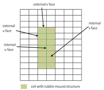
The implicit solver of the CMS uses a non-staggered grid for the basis of the numerical solution. The model identifies the cells where the rubble mound structures are located, as shown in Figure 2. The rubble mound resistance formulations are added to the x- and y-direction momentum equations for all the rubble mound cells. The same numerical algorithms are applied to solve the flow and sediment transport equations on the normal cells and rubble mound cells with the modifications made for rubble mound cells in Equations (3) and (4).
The CMS-Flow model uses a staggered grid for the bases of the numerical solution. Figure 1 shows a typical grid with a set of cells marked as containing a rubble mound structure. The momentum is calculated at the cell faces. For the purpose of implementing the rubble mound representation in the numerical solution algorithm, the faces are designated as external or internal as noted in Figure 1. The rubble mound resistance formulations are added to the x- and y-direction momentum equations for all internal and external faces. In general, the same numerical approximation conventions used for evaluating variables and gradients in the standard faces and can be found in the CMS documentation (Militello et al., 2004).
In the numerical solution, the effects of wind and wave radiation stress gradients are eliminated for all rubble mound cells. There are no additional modifications to the sediment transport algorithms, other than that noted in equation 5. Bedload can be transported into a rubble mound cell. Transport within a rubble mound cell will be greatly reduced by the lower flow speed, reduced energy and subsequent lower bottom stresses.
The rubble mound is specified in the CMS by identifying the cells containing the rubble mound structure, and specifying the structure porosity, nominal riprap or rock diameter, and the method for specifying resistance coefficients a and b.
Resistance Coefficients a and b:
The coefficients in Fochheimer’s resistance equation have been evaluated in a number of studies. Sidiropoulou et al. (2006) provides a review of proposed formulas. The formulas by Ward (1964) are:
| (5) |
where is the water dynamic viscosity and is the riprap or rock diameter. Kadlec and Knight (1996) suggested the following formulas:
| (6) |
Sidiropoulou et al. (2006) empirically derived:
| (7) |
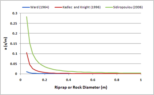
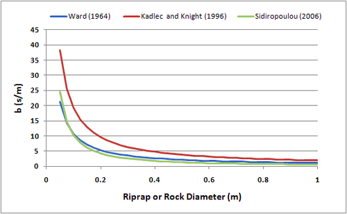
A plot of these functions for a porosity of 0.4 and a range of diameters from 0.05 to 1.0 meters is shown in Figure 2 and 3. The largest variation in values occurs for the smaller rock size for coefficient a. The variation for parameter b is smaller, less than a factor of two over the range of rock sizes considered.


Additional Information
This techical wiki was prepared and funded under the Coastal Inlets Research Program (CIRP) being conducted a the U.S. Army Engineer Research and Development Center, Costal and Hydraulics Laboratory. Questions about this technical note can be addressed to to Dr. Christopher W. Reed (Chris_Reed@URSCorp.com) of URS Corporation or Alejandro Sanchez (Alejandro.Sanchez@usace.army.mil). The CIRP Program Manager, Dr. Julie D. Rosati (Julie.D.Rosati@usace.army.mil), the assistant Program Manager, Dr. Nicholas C. Kraus (Nicholas.C.Kraus@usace.army.mil).
Test cases showing model verification and sensitivity are provided in Rubble Mound Tests
References
- Buttolph, A. M., C. W. Reed, N. C. Kraus, N. Ono, M. Larson, B. Camenen, H. Hanson, T. Wamsley, and A. K. Zundel, A. K. 2006. Two-dimensional depth-averaged circulation model CMS-M2D: Version 3.0, Report 2, sediment transport and morphology change. Coastal and Hydraulics Laboratory Technical Report ERDC/CHL-TR-06-7. Vicksburg, MS: U.S. Army Engineer Research and Development Center.
- Forchheim, Ph. "Wasserbevegung durch Boden" , Z. Ver. Deutsh. Ing., Vol. 45, 1901, p.1781-1788
- Kadlec H.R., Knight, L.R., 1996. Treatment Wetlands. Lweis Publishers.
- Melina G. Sidiropoulou Konstadinos N. Moutsopoulos Vassilios A. Tsihrintzis (2007). Determination of Forchheimer equation coefficients a and b. Hydrological Processes, Volume 21, Issue 4, 15, Pages: 534–554.
- Militello, A., Reed, C.W., Zundel, A.K., and Kraus, N.C. 2004. Two-Dimensional Depth-Averaged Circulation Model M2D: Version 2.0, Report 1, Technical Documentation and User’s Guide, ERDC/CHL TR-04-2, U.S. Army Research and Development Center, Coastal and Hydraulics Laboratory, Vicksburg, MS.
- Ward, J.C., 1964. Turbulent flow in porous media. Journal of Hydrualic Division, ASCE 90(5): 1-12