TR-08-13:Chapter4
Model Validation
Numerical models are validated by comparing model calculations to data and analytical solutions to determine the reliability of a model's individual or combined features. Data for model validation come from laboratory and field measurements, whereas analytical solutions are available in the literature and engineering manuals. Validation tests are essential benchmarks for evaluating both general features and the unique capabilities of numerical models.
This chapter describes and discusses nine examples, or cases, and four depth-limited breaking wave formulas. The CMS-Wave validation is shown for eight data sets from laboratory and field studies, two sets of analytical solutions, and two sets of semi-empirical calculations. The laboratory data are from experiments that have been conducted for idealized inlets, plain sloping beaches, and jetties. These data are examined for validation of wave breaking formulas, wave-current interaction, wave runup, and overall model performance at inlets and nearshore. Theoretical solutions for wave diffraction at a semi-infinite breakwater, a single gap, and multiple gaps in breakwaters are examined to evaluate the reliability of CMS-Wave calculations for simulating wave-structure interaction problems. The wind-wave growth capability of CMS-Wave is validated with semi-empirical relations given in the U.S Army Corps of Engineers Shore Protection Manual 1984) and Coastal Engineering Manual (Headquarters (HQ), USACE 2002).
The wave reflection capability of CMS-Wave was tested based on a laboratory experiment conducted for an idealized inlet protected by dual jetties (Seabergh et al. 2005). Both fully reflected and absorbing jetties were tested in the experiment. Details of the experiment, data, and CMS-Wave predictions and comparisons were summarized in (Lin et al. 2006b). This Technical Note also includes additional tests comparing CMS-Wave results to data for wave diffraction around and behind a shore-parallel breakwater and wave diffraction measurements by Seabergh et al. (2002) at the bay side of an inlet.
Case 1: Wave shoaling and breaking around an idealized inlet
Smith et al. (1998) conducted a laboratory study to investigate the wave-current interaction and the associated wave breaking in an idealized entrance with dual jetties. Figure 10 shows the bathymetry (depth in cm) of a relatively steep beach, and the arrangement of wave and current meters. The parallel contours were determined by the equilibrium profile equation from Dean (1977) with the scale factor of 0.24 cm1/3. The slope in the model extended to 18.2 cm mean low water depth and was then linearly transitioned to the basin floor at a depth of 30.4 cm. Two parallel jetties have a spacing of 3.7 m and extend 5.5 m offshore to protect the entrance channel where the depth varied from 9 to 12.8 cm. The inlet throat converged to a depth of 15.2 cm.
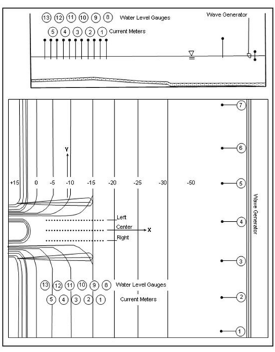
Figure 10. Idealized inlet and instrument locations.
Twelve conditions, Runs 1 through 12, were conducted for a wide range of values of wave and current parameters. In the experiment, Runs 1 to 4 were without a tidal current, and Runs 5 to 8 had a moderate steady-state ebb current of approximately 11 cm/sec at the inlet entrance. Runs 9 to 12 had a strong steady-state ebb current of approximately 22 cm/sec at the entrance. All waves were generated in the basin perpendicular to the shoreline by a unidirectional plunge-type generator driven by a TMA spectral shape with gamma (spectral peak enhancement parameter) of 3.3. In Runs 5 to 12, the wave-current interaction was created between incident waves that encountered the ebb tidal current. Table 5 presents the incident wave parameters (significant height Hs defined as 4 times the total energy density, spectral peak period Tp, and spectral peak frequency fp), and ebb current condition (speed U). Wave data were collected along one transect line seaward of the wave maker and three shore-normal transect lines in the entrance channel (Figure 10).
Table 5. Incident wave parameters and current conditions.
| Run | Hs '(cm)'a | Tp '(sec)'a | fp '(Hz)'b | U '(cm/sec)'c |
| 1 | 5.59 | 1.41 | 0.71 | 0 |
| 2 | 3.70 | 1.41 | 0.71 | 0 |
| 3 | 5.15 | 0.71 | 1.41 | 0 |
| 4 | 3.71 | 0.71 | 1.41 | 0 |
| 5 | 5.77 | 1.41 | 0.71 | 11.5 |
| 6 | 4.08 | 1.41 | 0.71 | 11.7 |
| 7 | 5.30 | 0.71 | 1.41 | 11.4 |
| 8 | 3.92 | 0.71 | 1.41 | 11.1 |
| 9 | 5.97 | 1.41 | 0.71 | 21.9 |
| 10 | 4.61 | 1.41 | 0.71 | 21.8 |
| 11 | 5.51 | 0.71 | 1.41 | 21.9 |
| 12 | 4.16 | 0.71 | 1.41 | 21.5 |
| a. Data averaged over gauges in front of wave generator. b. fp = 1/Tp. c. Averaged over current meters in the entrance channel. | ||||
CMS-Wave simulations were run in the laboratory scale. The grid domain covered the same rectangular area as the experiment basin. It consisted of 188 cross-shore and 401 along-shore square cells, each 10 cm ×10 cm. The incident wave input at the seaward boundary was a TMA-type unidirectional spectrum consisting of 30 frequency bins (0.5 to 3 Hz at 0.085-Hz increment) and 35 direction bins (covering a half-plane with 5-deg spacing). The 2D background input current fields for Runs 5-8 and 9-12 were prepared using the CMS-Flow, drives by different water levels specified at the inlet throat and sea boundaries. A water level difference of 3 cm was specified in the CMS-Flow to simulate a weak current field for Runs 5-8. A water level difference of 5 cm was specified in the CMS-Flow to generate a stronger current field for Runs 9-12. Figure 11 shows calculated ebb current fields in the steady-state condition. Both depth contours and current vector fields are symmetric with respect to the inlet channel center line in the model. Figures 12 and 13 show the measured and calculated current speeds along the inlet channel centerline. To test each of four wave breaking formulas described in Chapter 2, CMS-Wave was run in the basic mode (iwet = 0, ibf = 0, iark = 0, iarkr = 0, and akap = 1). For each run, the wave data collected in front of the wave generator was averaged and input as the incident wave condition.
Figures 14 to 16 compare measured and calculated wave heights along the entrance channel centerline for the null ebb current, moderate ebb current, and strong ebb current, respectively. For the null ebb current (Runs 1-4), the calculated wave height agrees well with measurements for all four wave breaking formulas. The extended Goda formula appears to agree slightly better with the measurements than the other three formulas; this is especially true for larger incident wave height (Runs 1 and 3) in the null tidal current condition. The performance of individual breaking formulas becomes different for shorter incident wave period irrespective of the incident wave height in these runs. This is evident in Figures 14 to 16 (Runs 3, 4, 7, 8, 11, and 12).
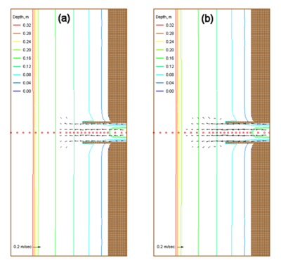
Figure 11. Input current fields for (a) Runs 5-8, (b) Runs 9-12, and save stations (square).
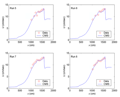
Figure 12. Measured and calculated current speeds along channel centerline, Runs 5-8.
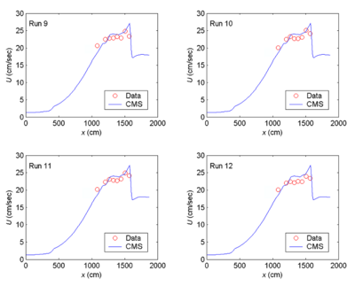
Figure 13. Measured and calculated current speeds along channel centerline, Runs 9-12.
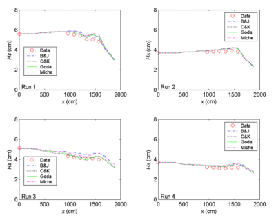
Figure 14. Measured and calculated wave heights along channel centerline, Runs 1-4.
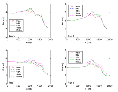
Figure 15. Measured and calculated wave heights along channel centerline, Runs 5-8.
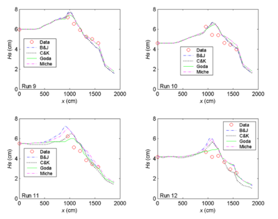
Figure 16. Measured and calculated wave heights along channel centerline, Runs 9-12.
With an ebb current present (Runs 5-12), the calculated wave height overall agrees better with the measurements for the incident wave of longer period (1.41 sec). This observation holds true regardless of large or small wave height and current magnitude, as shown in the upper panel in Figures 15 and 16 (Runs 5, 6, 9 and 10). For the shorter wave period (0.71 sec), the breaking formula by Battjes and Janssen (1978) and the Extended Miche formula (Battjes 1972; Mase et al. 2005b) tend to overestimate the wave height, whereas the formula by Chawla and Kirby (2002) and the Extended Goda formula (Sakai et al. 1989) compare better for wave height. The overall performance of these breaking formulas revealed that wave height estimates based on the Extended Goda formula, with or without the wave-current interaction, were consistently better than estimates obtained with the other formulas.
Case 2: Waves breaking on plane beach
Visser (1991) conducted eight laboratory experiments, labeled as Exp. 1 to Exp. 8, with monochromatic incident waves that broke on a planar beach and generated a longshore current. A large data set of wave, current, and water level was collected for a number of incident wave conditions tested for two beach slopes (1:10 and 1:20) and two different bottom roughnesses. In this report, Visser Exps. 4 to 7 were selected for model validation because these have the same bottom composite slopes and the most complete measurements. The beach had a 1:10 slope for the first seaward 1-m distance, 1:20 slope for the next 5-m distance, and a flat bottom for the next 5.9 m to the wave generator. Exps. 4 through 6 were performed on a concrete bed, where the bottom friction is expected to be small and, therefore, neglected in the wave numerical simulation. For Exp. 7, the 1:20 slope bottom was roughened by a thin layer (0.5-1.0 cm) of gravel grouted on the concrete floor. Table 6 presents the incident wave conditions.
Table 6. Incident wave conditions.
| Exp. | Hs '(cm)'a | Tp '(sec)'a | fp '(Hz)'b | ' '(deg)c |
| 4 | 7.8 | 1.02 | 0.98 | 15.4 |
| 5 | 7.1 | 1.85 | 0.54 | 15.4 |
| 6 | 6.9 | 0.70 | 1.43 | 15.4 |
| 7 | 7.8 | 1.02 | 0.98 | 15.4 |
| a. Monochromatic wave. b. fp=1/Tp. c. Wave direction relative to shore-normal. | ||||
CMS-Wave was run at the laboratory scale. The model grid consisted of 90 cross-shore and 243 alongshore square cells, each 10 cm × 10 cm, to cover the entire basin in these experiments. The spectral transformation was computed in CMS-Wave on 11 frequency bins (covering the range of +/ 0.05 Hz of the incident monochromatic wave frequency at 0.01-Hz increment) and 35 direction bins (covering a half-plane with 5-deg spacing). The incident monochromatic, unidirectional wave spectrum was specified in a single frequency and direction bin at the seaward boundary. The input current and water level fields were interpolated across shore and averaged alongshore from the data. For Exp. 7 with the gravel floor, a constant bottom friction coefficient cf of 0.01 was specified in CMS-Wave and was found to produce good wave estimates.
Figure 17 shows an example of input current and water level fields to CMS-Wave for the Exp. 4. Figure 18 compares the measured and calculated across shore wave heights for Exp. 4 through 7. The calculated wave height agrees well with the measurements for four different depth-limiting breaking formulas implemented in CMS-Wave.
Case 3: Wave runup on impermeable uniform slope
Wave runup on a uniform slope calculated by CMS-Wave was compared to two laboratory experiments, one experiment conducted by Ahrens and Titus (1981) the other by Mase and Iwagaki (1984). Incident random waves were generated in both experiments in a wave flume consisting of a flat bottom connected to a slope. The experiments by Ahrens and Titus included 275 wave conditions (Ahrens and Heimbaugh 1988), with the significant wave heights ranging from 4 to 20 cm and spectral peak periods from 1.1 to 4.5 sec, on six different uniform slopes at 1:1, 2:3, 1:2, 2:5, 1:3, and 1:4. The experiments by Mase and Iwagaki tested 120 wave conditions (Mase 1989), with significant wave heights ranging from 2.7 to 11 cm and spectral peak periods from 0.8 to 2.5 sec, on four uniform slopes at 1:5, 1:10, 1:20, and 1:30.
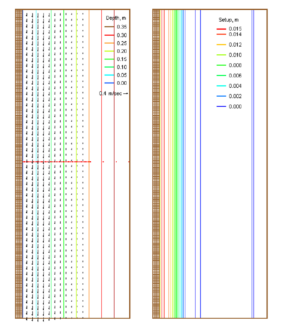
Figure 17. Input current and wave setup fields with save stations (dot) for Exp. 4.
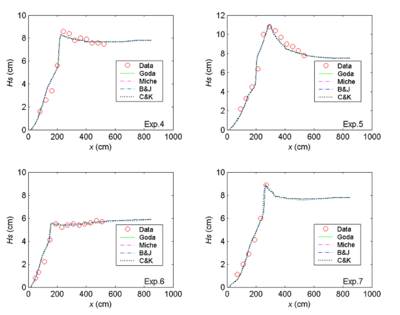
Figure 18. Measured and calculated wave heights, Exp. 4-7.
CMS-Wave was run at the laboratory scale. The model grid consisted of 1,750 cross-shore and 100 alongshore square cells, each 2 cm × 2 cm, to cover a 10-m-long flat bottom and a 25-m-long slope section. The spectral transformation was computed in CMS-Wave on 30 frequency bins (from 0.1 to 1.26 Hz at 0.04-Hz increment for the Ahrens and Titus experiments, and from 0.02 to 2.05 Hz at 0.07-Hz increment for the Mase and Iwagaki experiments) and 35 direction bins (covering a half-plane with 5-deg spacing). Bottom friction was neglected (cf = 0) in the numerical simulations.
Figure 19 shows the measured and calculated 2% exceedance wave runup (R2) for all experiments conducted by Ahrens and Titus (1981) and by Mase and Iwagaki (1984). Table 7 presents the mean bias (mean of calculated minus measured) and correlation coefficients (equivalent to normalized root-mean-square errors) between the measured and calculated 2% exceedance wave runups. The CMS-Wave calculated 2 % exceedance wave runups correlate well with the measured values for all test slopes, especially for more gentle slopes (1:5 to 1:30). The mean bias of calculated runups is generally small in all cases except for the steepest slope (1:1) condition in which CMS-Wave tends to overestimate the runup (open-circles in Figure 19). For steeper slopes, more wave reflection with less wave energy loss on the slope can affect the wave runup calculations. Testing of the wave reflection effect on wave runup for a steep slope is underway.
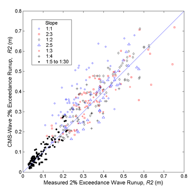
Figure 19. Measured and calculated 2% exceedence wave runup.
Table 7. Statistics of measured and calculated wave runup.
| Slope | Mean of Calculated '''R'''2 (m) | Mean of Measured '''R'''2 | Mean Bias (m) | Correlation Coefficient |
| 1:1 | 0.40 | 0.29 | 0.11 | 0.74 |
| 2:3 | 0.41 | 0.39 | 0.02 | 0.86 |
| 1:2 | 0.44 | 0.43 | 0.01 | 0.90 |
| 2:5 | 0.37 | 0.37 | 0.00 | 0.88 |
| 1:3 | 0.33 | 0.33 | 0.00 | 0.79 |
| 1:4 | 0.29 | 0.28 | 0.01 | 0.72 |
| 1:5 - 1:30 | 0.09 | 0.09 | 0.00 | 0.91 |
Case 4: Wave diffraction at breakwater and breakwater gap
The wave diffraction calculated by CMS-Wave was compared to diffraction diagrams in the Shore Protection Manual (1984) and Coastal Engineering Manual (HQUSACE 2002) based on the Sommerfeld solution for a flat bottom. These diagrams were originally compiled by Wiegel (1962) for a straight semi-infinite long breakwater and by Johnson (1952) for a breakwater gap for monochromatic incident waves impinging on these structures from different directions. The computational domain was a square grid consisting of 101 x 101 cells with cell size of 20 m x 20 m. The breakwater was specified as dry cells in a column aligned with the seaward boundary. A uniform water depth of 1,000 m was specified to present deepwater waves. The incident wave height was 1 m, and wave period was 8 sec (0.125 Hz). This incident wave corresponds to a wavelength of 100 m. The wave diffraction was simulated in CMS-Wave on 10 frequency bins (from 0.06 Hz to 0.15 Hz with 0.01-Hz increment) and 35 direction bins (covering a half-plane with 5-deg spacing).
Figure 20 shows calculated wave height normalized by the incident height, (dash-dot line) and the wave diffraction diagram (solid line) for the semi-infinite long breakwater. The incident wave is perpendicular to the breakwater. In the numerical simulation, the incident wave was provided in a single frequency and direction bin. The diffraction intensity value was set to 4 to simulate the maximum diffraction allowed in CMS-Wave, and the bottom friction loss is neglected in the calculation.
The normalized wave height under wave diffraction is designated as the diffraction coefficient, K'. The graph coordinates are normalized by the wavelength, and plots are in units of wavelength, L, such that the diffraction diagram can represent the deep-water wave as well as shallow to intermediate water conditions. Calculated wave diffraction coefficients agree well with the diffraction diagram. In practical applications, the direction of diffracted waves is as important as the wave height. Figures 21 to 23 show wave vector (height and direction) plots for the semi-infinite long breakwater for incident waves approaching from -45, 0, and 45 deg, respectively. As can be seen from these figures, calculated waves are diffracted well into the shadow region behind the breakwater.
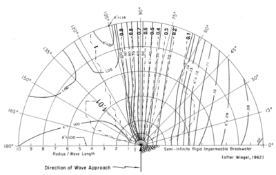
Figure 20. Wave diffraction diagram and calculated '''K' '(dash-dot) for a breakwater.
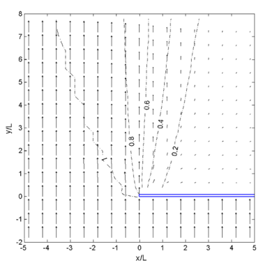
Figure 21. Calculated wave vectors and '''K''', 0 deg incident wave.
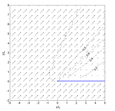
Figure 22. Calculated wave vectors and '''K''', -45 deg incident wave.
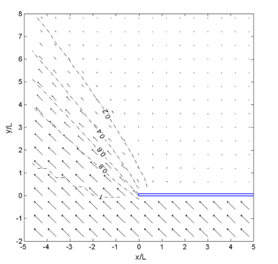
Figure 23. Calculated wave vectors and '''K''', 45 deg incident wave.
Figures 24 and 25 show wave diffraction diagrams (Shore Protection Manual 1984; HQUSACE 2002) and calculated wave heights for the breakwater gap width, B = L, and B = 2L, (e.g. equal to one and two wavelengths) respectively. The incident wave direction is normal to the breakwater. The diffraction intensity value is set to 2 for the gap width B = L and 3 for the B = 2L. Bottom friction was 0. Calculated wave diffraction coefficients agree well with the diffraction diagram in these breakwater gap simulations. Figures 26 to 28 show examples of wave vector plots for the breakwater gap B = 2L with the wave approaching angle from -45, 0, and 45 deg, respectively. Calculated wave height and directions from incident angles of -45 and 45 deg are symmetric about the center line. Calculated wave directions clearly show diffraction through the gap behind the breakwater.
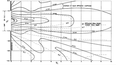
Figure 24. Wave diffraction diagram and calculated '''K '(dash-dot) for a gap, '''B '= 2'''L'''.
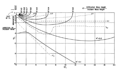
Figure 25. Wave diffraction diagram and calculated '''K '(dash-dot) for a gap, '''B '= '''L'''.
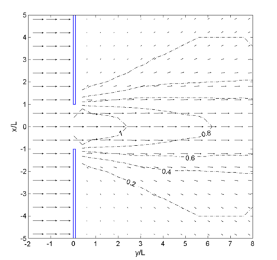
Figure 26. Calculated wave vectors and '''K 'for gap '''B '= 2'''L''', 0 deg incident wave.
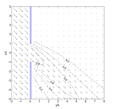
Figure 27. Calculated wave vectors and '''K 'for gap '''B '= 2'''L''', -45 deg incident wave.
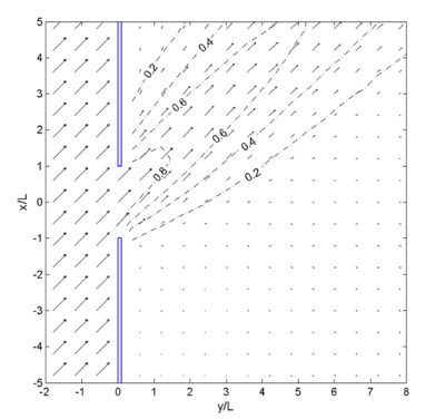
Figure 28. Calculated wave vectors and '''K 'for gap '''B '= 2'''L''', 45 deg incident wave.
Case 5: Wave generation in fetch-limited condition
For wind wave predictions, the Sverdrup-Munk-Bretschneider (SMB) method was developed in the 1950s for deep water conditions. In shallow water applications, the SMB method was modified for constant depth by the U.S. Army Corps of Engineers and it has been widely used in engineering projects. Additional information about the SMB method can be found in the Shore Protection Manual (1984). Wind wave generation/growth capability implemented in CMS-Wave is validated by comparison to the modified SMB curves.
Numerical simulations were conducted for a flat bottom seabed of 20-m constant depth. Constant wind speeds of 10, 20, and 35 m/sec were applied to a computational domain consisting of 10 100 cells with cell size 200 m 200 m. The wind blew along the 20-km-long axis of the grid. The wave energy input at the upwind boundary of modeling area was set to 0, and the wave generation was calculated on a spectral grid of 30 frequency bins (0.12 to 0.35 Hz with 0.008-Hz increment) and 35 direction bins (covering a half-plane with 5-deg spacing).
Figure 29 compares the calculated wave height and wave period with results from the Shore Protection Manual. Calculated wave height values agree well in these simulations for fetch greater than 5 km. For a fetch less than 5 km and at greater wind speeds, CMS-Wave predicts lower wave height than the Shore Protection Manual method. Over short fetches, wave height calculated by CMS-Wave increases more linearly with the length of fetch, compared to the Shore Protection Manual method.
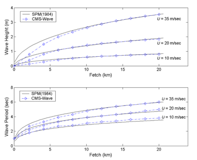
Figure 29. Comparison of calculated wave generation and SMB curves.
Case 6: Wave generation in bays
Wave data collected at Rich Passage, WA, and in southern Chesapeake Bay, VA, were analyzed for validation of wave generation and growth in bays by CMS-Wave. Rich Passage is a tidal strait separating Bainbridge Island south shore and Kitsap Peninsula in western Puget Sound. A wave gauge (LT14) was installed near the southeast shore of Bainbridge Island (Osborne and MacDonald 2005). Figure 30 shows the location of Rich Passage and the wave gauge (47º35'28"N, 122º33'56"W). Strong tidal currents prevailing in the vicinity of the gauge are the main concerns to navigation, and these currents can interact with the local wave generation.
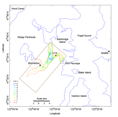
Figure 30. Modeling grid domain for Rich Passage and wave gauge location (LT14).
The computational domain for Rich Passage is a rectangular area that includes 160 350 square cells of cell size 50 m 50 m. CMS-Wave simulations were performed for two relatively strong wave conditions, coexisting with a persistent southeast wind observed on 29 March 2005. The input for each simulation includes a pre-calculated tidal current field and constant wind speed. The wave generation and interaction with a current present were computed on a spectral grid of 30 frequency bins (0.04 to 0.33 Hz with 0.01-Hz increment) and 35 direction bins with 5-deg spacing of a half-plane.
Figure 31 shows the input current field and calculated wave field for a typical maximum flood condition and input wind speed of 8 m/sec, blowing from 220 deg, at 00:40 GMT, 29 March 2005. Figure 32 shows the input current field and calculated wave field for a strong ebb condition and wind speed of 11 m/sec, blowing from 220 deg, at 19:20 GMT of the same day. Table 8 presents the measured and calculated wave heights at the wave gauge location of LT14. In both simulations, the calculated wave height is in good agreement with the measurements.
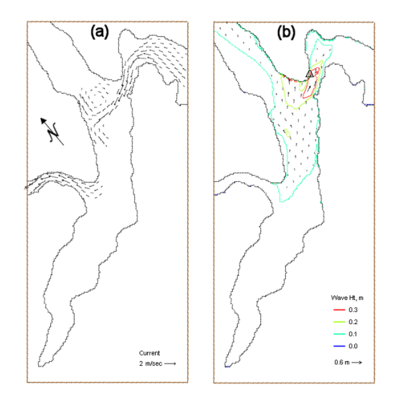
Figure 31. (a) Input current, and (b) calculated wave fields at 00:40 GMT, 29 March 2005.
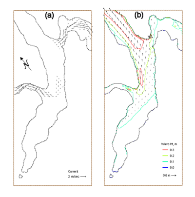
Figure 32. (a) Input current, and (b) calculated wave fields at 19:20 GMT, 29 March 2005.
Table 8. Comparison of measured and calculated wave height at wave Gauge LT14.
| Date | Time (GMT) | Wind Speed (m/sec) | Wind Direction (deg) | Measured '''Hs '(m) | Calculated 'Hs '(m) |
| 29 March 2005 | 00:40 | 8 | 220 | 0.19 | 0.18 |
| 29 March 2005 | 19:20 | 11 | 220 | 0.28 | 0.27 |
The bathymetric grid for the Chesapeake Bay region is 295 km long (northing) and 100 km wide (easting) and has a horizontal resolution of 500 m. A CMS-Wave simulation was performed for a strong northeasterly wind that occurred on 27 February 1993. Wave data are available in the lower bay at the Thimble Shoal Light (TSL) gauge from 1988 to 1995 for model validation (VIMSWAVE/ VIMSWAVE.htm http://www.vims.edu/physical/research/ VIMSWAVE/ VIMSWAVE.htm). The coordinates of the TSL gauge are 37º2.4'N, 76º11.9'W, and the nominal water depth is 5.5 m. Wind data are available in the middle of the narrow upper bay at a NOAA C-MAN sta TPLM2 (38º53.5'N, 76º26.1'W) (Chesapeake_Bay.shtml http://www.ndbc.noaa.gov/maps/ Chesapeake_Bay.shtml). Demirbilek et al. (2007) and Lin et al. (2006a) discuss storm surge modeling resulting from hurricanes and northeasters in Chesapeake Bay and the vicinity.
Figure 33 shows the model bathymetric domain and calculated wave field under a steady northerly wind (15 m/sec wind speed blowing from north) at 12:00 GMT, 27 February 1993. Figure 34 compares measured and calculated directional wave spectra (wave energy density distribution shown as contours in m2 sec/radian) at sta TSL. The corresponding significant wave height is four times the square root of the total wave energy, an integrated quantity of wave energy density over the frequency and direction domains. The measured and calculated wave heights are 1.00 m and 1.01 m, respectively. The magnitude and direction of the calculated wave spectrum agree well with the measurements. Because the nonlinearity of energy transfer amongst spectral components is not included in this simulation, the calculated spectrum is skewed more to higher frequency (Demirbilek et al. 2007; Lin et al. 2006a).
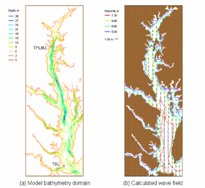
Figure 33. (a) Model domain and (b) calculated wave field at 12:00 GMT, 27 February 1993.
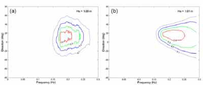
Figure 34. (a) Measured, and (b) calculated spectra at TSL, 12:00 GMT, 27 February 1993.
Case 7: Large waves at Mouth of Columbia River
The Mouth of Columbia River (MCR) is a shared estuary between the States of Oregon and Washington. The numerical grid covers a rectangular domain 22.7 km long (northing) and 25.8 km wide (easting) with a fine horizontal resolution of 20.7 m. Directional wave measurements were collected between the north and south jetties from 1 August to 9 September 2005, at five monitoring stations by the U.S. Army Engineer District, Portland (Demirbilek et al. 2008). Table 9 presents coordinates and nominal depth, relative to mean tide level (mtl), of these monitoring stations. The incident wave spectrum is based on offshore Buoy 46029 (46º7'N, 124º30.6'W), maintained by the National Data Buoy Center (NDBC) since 1984 (http://www.ndbc.noaa.gov). Figure 35 shows the model bathymetric domain and wave gauge stations.
Table 9. Coordinates of wave monitoring stations at MCR (August-September 2005).
| Station | Coordinates | Depth, mtl (m) |
| 1 | 46o16'16"N, 124o03'23"W | 9.7 |
| 2 | 46o15'47"N, 124o03'29"W | 12.9 |
| 3 | 46o15'27"N, 124o03'13"W | 21.7 |
| 4 | 46o15'04"N, 124o03'46"W | 14.2 |
| 5 | 46o14'24"N, 124o03'58"W | 10.4 |
Strong tidal and river currents are observed at the MCR with a typical average current magnitude of 2 m/sec. To investigate model performance for waves only, three large incident waves during slack tide from the data collection period were selected for the simulation. These large wave events occurred at 10:00 GMT on 7 August, at 00:00 GMT on 30 August, and at 18:00 GMT on 9 September 2005. Figure 36 shows sample time-series of wind and wave data collected from Buoy 46029 and sta 4 and 5 at the MCR. The effects of waves interacting with tidal current at sta 4 and 5 are clearly seen in the data as strong daily fluctuations of wave height, period and direction. Wind forcing was taken from the buoy measurements and adjusted to a 10-m elevation based on the 1/7 power law (Shore Protection Manual 1984; HQUSACE 2002).
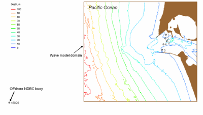
Figure 35. Wave model domain and directional wave data-collection stations.
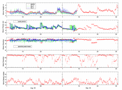
Figure 36. Wave and wind data collected at Buoy 46029, sta 4 and 5.
In the simulation at 10:00 GMT on 7 August 2005, the input wave condition parameters at the model grid seaward boundary were 2.0 m, 8.3 sec, and 300 deg (WNW). Buoy 46029 reported a moderate and steady wind of 7.7 m/sec from 344 deg (NNW). In the simulation of 00:00 GMT on 30 August 2005, the model seaward boundary input was a wave of 2.2 m, 11.1 sec, and 284 deg (NWW). A weak wind of 3.3 m/sec from 235 deg (SW) was observed at the buoy. At 18:00 GMT on 9 September, the incident wave condition was a wave of 4.0 m, 10 sec, and 307 deg (NW). The corresponding buoy wind was 7.6 m/sec from 311 deg (NW). Directional wave spectra from Buoy 46029 served as input, discretized in 30 frequency bins (0.04 to 0.33 Hz with 0.01-Hz increment) and 35 direction bins (covering a half-plane with 5-deg spacing), at the seaward boundary.
Figures 37 and 38 show calculated wave fields, with and without wind input, at 10:00 GMT on 7 August, and 18:00 GMT on 9 September, respectively. These simulations show greater calculated waves approaching the MCR with wind input than without wind input. At 18:00 GMT on 9 September 2005, the wave growth with wind input was significant because the wind direction was practically the same as the mean wave direction. Figures 39 to 43 show measured and calculated directional spectra (in m2 sec/radian) at 10:00 GMT on 7 August 2005, at five monitoring stations, respectively. Figures 44 to 48, respectively, show measured and calculated directional spectra (in m2 sec/radian) at 00:00 GMT on 30 August 2005 at five monitoring stations. Wind forcing was included in these wave-spectrum calculations.
At 18:00 GMT on 9 September 2005, directional wave data were only available at sta 4 and 5. Figures 49 and 50 compare measured and calculated directional spectra for these two stations. The magnitude and direction of the calculated spectra compare well to the measurements. Because the nonlinear wave-wave interaction is not calculated in the model and the effect can be strong in shallow water, the calculated spectra are narrower in direction and wider in frequency compared with the measured spectra.
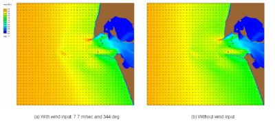
Figure 37. Calculated waves with and without wind input, 10:00 GMT, 7 August 2005.
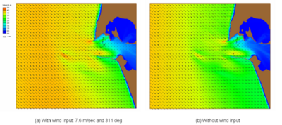
Figure 38. Calculated waves with and without wind input, 18:00 GMT, 9 September 2005.
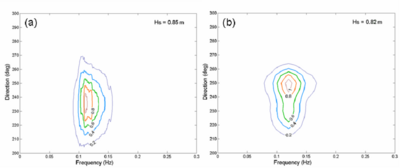
Figure 39. (a) Measured and (b) calculated spectra at sta 1, 10:00 GMT, 7 August 2005.
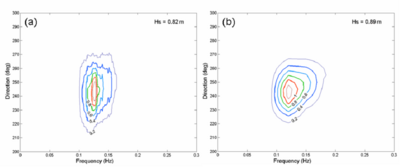
Figure 40. (a) Measured and (b) calculated spectra at sta 2, 10:00 GMT, 7 August 2005.
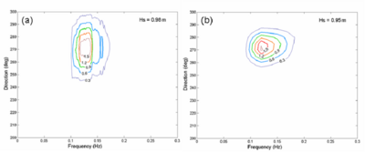
Figure 41. (a) Measured and (b) calculated spectra at sta 3, 10:00 GMT, 7 August 2005.
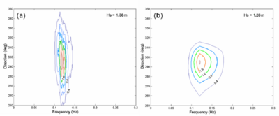
Figure 42. (a) Measured and (b) calculated spectra at sta 4, 10:00 GMT, 7 August 2005.
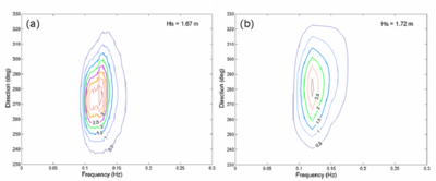
Figure 43. (a) Measured and (b) calculated spectra at sta 5, 10:00 GMT, 7 August 2005.
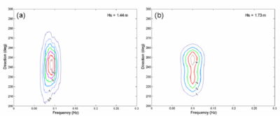
Figure 44. (a) Measured and (b) calculated spectra at sta 1, 00:00 GMT, 30 August 2005.
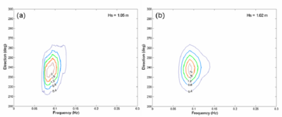
Figure 45. (a) Measured and (b) calculated spectra at sta 2, 00:00 GMT, 30 August 2005.
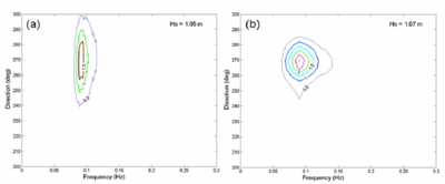
Figure 46. (a) Measured and (b) calculated spectra at sta 3, 00:00 GMT, 30 August 2005.
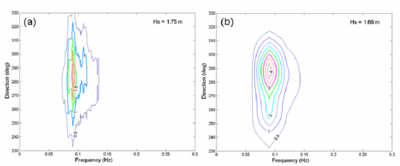
Figure 47. (a) Measured and (b) calculated spectra at sta 4, 00:00 GMT, 30 August 2005.
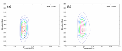
Figure 48. (a) Measured and (b) calculated spectra at sta 5, 00:00 GMT, 30 August 2005.
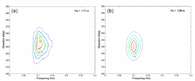
Figure 49. (a) Measured and (b) calculated spectra at sta 2, 18:00 GMT, 9 September 2005.
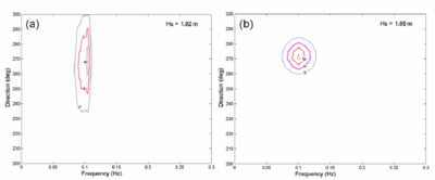
Figure 50. (a) Measured and (b) calculated spectra at sta 3, 18:00 GMT, 9 September 2005.
Case 8: Wave transformation in fast mode and variable-rectangular-cell grid
CMS-Wave can run more efficiently on a grid with variable rectangular cells than with constant spacing cells, especially for a large computational domain such as in the previous case of wave transformation at the Mouth of Columbia River (Figure 35). For quick applications, CMS-Wave can also be run in a fast mode to reduce the runtime. The efficiency of CMS-Wave in the fast mode and variable-rectangular-cell grid is compared to the standard mode and constant-rectangular-cell grid for two extreme winter storms observed offshore of the MCR. Wind forcing is not considered in the comparison. Table 10 lists the two storm waves recorded offshore at Buoy 46029 (Demirbilek et al. 2008). The first storm occurred on 14 December 2001 with a 10.1 m significant wave height directed from the northwest. The second storm occurred from the southwest on 4 February 2006 with a 13.8 m significant wave height. Storms do not occur often, but can be harmful to the MCR jetties and adjacent beaches.
Table 10. Waves in two extreme storms observed offshore of MCR at Buoy 46029.
| Date | Time (GMT) | Wave Height (m) | Wave Period (sec) | Wave Direction (deg) |
| 14 December 2001 | 12:00 | 10.1 | 14.3 | 297 |
| 4 February 2006 | 13:00 | 13.8 | 16.7 | 230 |
Both the variable-cell grid and constant-cell grid cover the same computational domain (22.7 km 25.8 km). The cell dimension is 20.7 m 20.7 m in the constant-cell grid. For the variable-cell grid, the cell dimension increases transitionally from 20.7 m 20.7 m at the entrance area to 103.3 m 103.3 m toward the corner areas of the model domain. There are a total of 1,100 1,250 cells in the constant-cell grid, but only 405 411 cells in the variable-cell grid. The CMS-Wave is more efficient for the variable-cell grid because the total number of cells in the computation is less than in the variable-cell grid than in the constant-cell grid. Figure 51 shows the variable-cell grid. Directional wave spectra from Buoy 46029 served as input, discretized in 30 frequency bins (0.04 to 0.33 Hz with 0.01-Hz increment) and 35 direction bins (covering a half-plane with 5-deg spacing), at the seaward boundary.
Figure 52 shows calculated wave fields of the 14 December 2001 storm for the constant-cell grid and variable-cell grid in standard mode. Similar to Figure 52, Figure 53 shows calculated wave fields for the same simulations in the fast mode. Figure 54 shows calculated wave fields of the 4 February 2006 event for the constant-cell grid and the variable-cell grid in the fast mode. The difference in calculated wave fields is apparent, but small between simulations from a constant-cell grid to a variable-cell grid and from a standard mode to a fast mode.
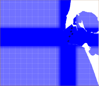
Figure 51. CMS-Wave variable-cell grid and five monitoring stations at MCR.
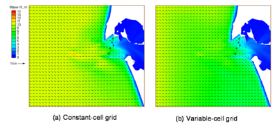
Figure 52. Calculated wave fields in standard mode, 12:00 GMT, 14 December 2001.
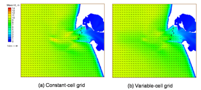
Figure 53. Calculated wave fields in fast mode, 12:00 GMT, 14 December 2001.
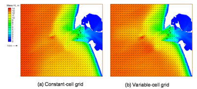
Figure 54. Calculated wave fields in fast mode, 13:00 GMT, 4 February 2006.
Tables 11 to 13 compare the total computer runtimes and calculated significant wave heights and spectral mean directions for the two extreme wave events at five monitoring stations (Table 9), respectively. The wave simulation on the variable-cell grid is approximately four times faster than the constant-cell grid. The computer run time for the fast mode is approximately 1/8 of the standard mode. The difference in calculated wave height at the five monitoring stations is small between the constant-cell grid and variable-cell grid, but it is relatively large between the standard mode and fast mode. The difference in calculated wave direction at five monitoring stations is small overall.
Table 11. Total computer runtime for two storm wave events at MCR.
| Grid | Run Mode | Total Run Time |
| Constant-cell | Standard | 17 min |
| Constant-cell | Fast | 2 min |
| Variable-cell | Standard | 4 min |
| Variable-cell | Fast | 35 sec |
Table 12. Calculated wave height (m) and direction (deg), 12:00 GMT, 14 December 2001.
| Sta | Constant-cell Standard mode | Variable-cell Standard mode | Constant-cell Fast Mode | Variable-cell Fast mode |
| 1 | 4.9 (239) |
5.1 (239) |
4.4 (234) |
4.7 (234) |
| 2 | 3.5 (237) |
3.8 (237) |
3.8 (239) |
4.0 (239) |
| 3 | 3.6 (264) |
3.7 (264) |
4.0 (259) |
4.3 (259) |
| 4 | 6.3 (280) |
6.5 (280) |
5.7 (272) |
6.0 (272) |
| 5 | 7.1 (276) |
7.1 (273) |
6.3 (279) |
6.8 (278) |
| NOTE: Wave direction is shown in parentheses. | ||||
Table 13. Calculated wave height (m) and direction (deg), 13:00 GMT, 4 February 2006.
| Sta | Constant-cell Standard mode | Variable-cell Standard mode | Constant-cell Fast Mode | Variable-cell Fast mode |
| 1 | 7.0 (225) |
7.1 (226) |
6.2 (230) |
6.3 (230) |
| 2 | 6.1 (223) |
6.3 (225) |
5.6 (231) |
5.9 (231) |
| 3 | 5.9 (248) |
6.6 (249) |
5.1 (250) |
5.5 (249) |
| 4 | 7.6 (252) |
8.8 (256) |
7.5 (261) |
8.0 (261) |
| 5 | 4.6 (237) |
5.3 (239) |
5.5 (262) |
5.8 (260) |
| NOTE: Wave direction is shown in parentheses. | ||||
Case 9: Wave transformation over complicated bathymetry with strong nearshore current
Laboratory experiments on wave transformation over a complicated bathymetry were conducted in the Research and Development Department of the Kansai Electric Power Co. Inc, Japan (Zheng et al. 2008). The physical model was built in a wave basin 20 m long and 38 m wide. The model to prototype scale was 1:125. Figure 55 shows the nearshore bathymetry and data-collection locations (circles). A snake-type wave maker generated incident wave spectra at the offshore boundary. Wave conditions included directional and unidirectional spectra. The input significant wave was 7.3 cm and 1.21 sec, simulating a 100-year return period. The directional spectrum was based on the Mitsuyasu distribution (Mitsuyasu and Honda 1982) with the spreading of direction in a standard deviation of 20 deg symmetric to the center angle.
Figure 56 displays measured directional and unidirectional wave height contours as well as the current induced by breaking waves. The wave-induced longshore current direction is from north to south in the physical model. The current can become strong at the concave shoreline (the maximum current speed reaches 0.25 m/sec in the model or equivalent to 2.7 m/sec in the prototype for unidirectional waves), where the incident waves converge and break toward the shore. The current outside the surf zone is overall weak (less than 0.05 m/sec) and opposite the wave propagation direction.
In this section, four depth-limited wave breaking criteria are examined with laboratory data.
Numerical simulations were carried out in the laboratory scale. The model grid domain is the same as the laboratory basin with the grid cell size of 0.2 m 0.2 m. A standard JONSWAP spectrum was generated for the incident waves, consisting of 10 frequency bins and 36 direction bins. The current velocity in each cell was interpolated from the measurements. The variation of water level caused by wave setup was not considered in the simulations. Bottom friction was set to 0 in the model.
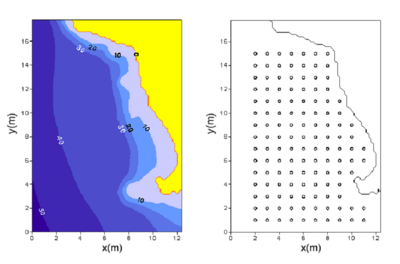
Figure 55. Bathymetry (left) in meters and locations of wave and current meters (right).
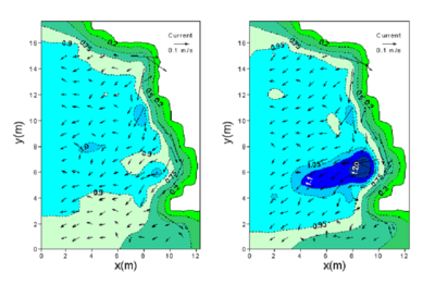
Figure 56. Measured current and normalized wave height contours for directional (left) and unidirectional (right) incident waves.
Extended Miche formula
Figures 57 and 58 show calculated wave height contours for directional and unidirectional incident waves, with and without a current present using the Extended Miche breaking formula. The numerical result is more accurate with the background current included in the calculation.
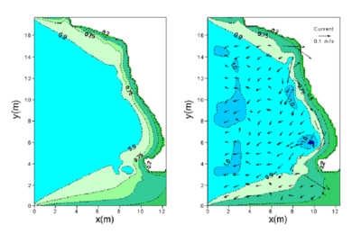
Figure 57. Calculated wave height contours for directional incident waves without current (left) and with current (right) by the Extended Miche formula with coefficient of 0.14.
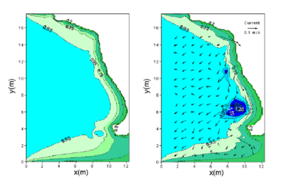
Figure 58. Calculated wave height contours for unidirectional incident waves without current (left) and with current (right) using the Extended Miche formula with coefficient of 0.14.
Figure 59 compares measured and calculated wave heights, normalized by the incident wave height (H1/3)0 for directional and unidirectional incident waves. The calculated wave height is typically within 20 percent of the measured height. The +/- 20 percent range lines are shown in dash-dotted lines in Figure 59. The predictions with the breaker coefficient of a = 0.129 are similar to those with a = 0.14. The simulations tend to overestimate the wave height if the measured normalized height is less than 0.75. Figures 60 and 61 compare measured and calculated wave heights along the longitudinal (parallel to y-axis) and transverse (parallel to x-axis) transects for directional and unidirectional incident waves, respectively. The simulation with current predicts the wave height enhancement well, although it tends to slightly over-predict the height in front of the headland (convex shoreline).
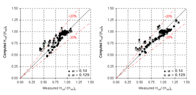
Figure 59. Measured versus calculated wave heights for directional (left) and unidirectional (right) incident waves with the Extended Miche formula.
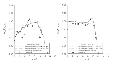
Figure 60. Normalized wave height comparisons of directional waves along longitudinal (left) and transverse (right) transects with the Extended Miche formula.
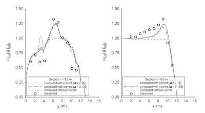
Figure 61. Normalized wave height comparisons of unidirectional waves along longitudinal (left) and transverse (right) transects with the Extended Miche formula.
Extended Goda formula
Figures 62 and 63 show wave height contours for directional and unidirectional incident waves with and without a current calculated with the Extended Goda formula (Sakai et al. 1989). The model prediction is more accurate with current than without current. However, the simulation based on the Extended Goda formula generally overpredicts the wave height in front of the headland (convex shoreline). Figure 64 compares normalized wave heights with the measurements. The differences between measured and calculated heights are typically smaller than 20 percent. The prediction based on a breaker coefficient of 0.15 is slightly better than 0.17. The simulations tend to overestimate the wave height if the measured normalized height is less than 0.75. Figures 65 and 66 compare measured and calculated wave heights along the longitudinal and transverse transects for directional and unidirectional incident waves, respectively. The model predicts the wave height well in both longitudinal and transverse directions with current.
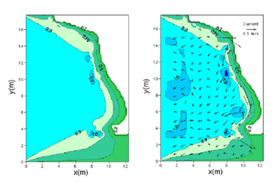
Figure 62. Calculated wave height contours for directional incident waves without current (left) and with current (right) by the Extended Goda formula with coefficient of 0.17.
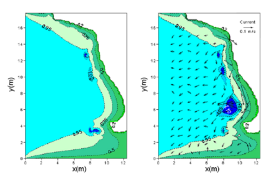
Figure 63. Calculated wave height contours for unidirectional incident waves without current (left) and with current (right) using the Extended Goda formula with coefficient of 0.17.
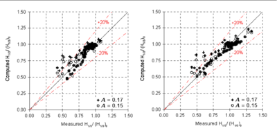
Figure 64. Measured versus calculated wave heights for directional (left) and unidirectional incident waves (right) with the Extended Goda formula.
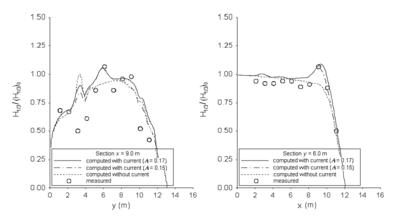
Figure 65. Normalized wave height comparisons of directional incident waves along longitudinal (left) and transverse (right) transects with the Extended Goda formula.
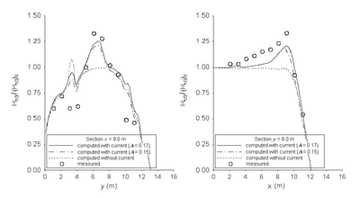
Figure 66. Normalized wave height comparisons of unidirectional incident waves along longitudinal (left) and transverse (right) transects with the Extended Goda formula.
Battjes and Janssen formula
Figures 67 and 68 show calculated wave height contours for directional and unidirectional incident waves with and without a current present using the Battjes and Janssen (1978) breaking formula. The model performs well in simulating the wave height increase in front of the concave shoreline if the current is included, whereas the model performs poorly without the current. Figure 69 compares calculated wave heights with measurements. The calculated height generally falls within 20 percent of the measurements. Figures 70 and 71 compare the measured and calculated normalized significant wave height along the longitudinal and transverse transects for directional and unidirectional incident waves, respectively. The predictions including the current agree well with the measurements, especially in the area where waves encounter the strong nearshore current. In contrast to the overpredictions by the Extended Miche and Extended Goda formulas, the calculated wave height in front of the headland agrees well with the measurements.
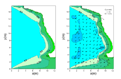
Figure 67. Calculated wave height contours for directional incident waves without current (left) and with current (right) by the Battjes and Janssen formula.
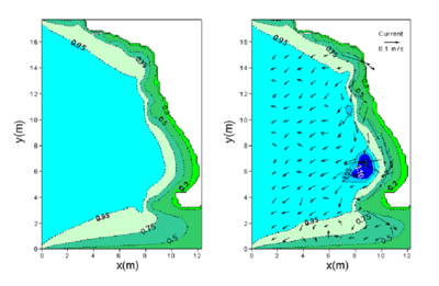
Figure 68. Calculated wave height contours for unidirectional waves without current (left) and with current (right) by the Battjes and Janssen formula.
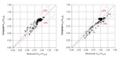
Figure 69. Measured versus calculated wave heights for directional (left) and unidirectional incident waves (right) with the Battjes and Janssen formula.
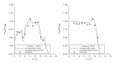
Figure 70. Normalized wave height comparisons of directional incident waves along longitudinal (left) and transverse (right) transects with the Battjes and Janssen formula.
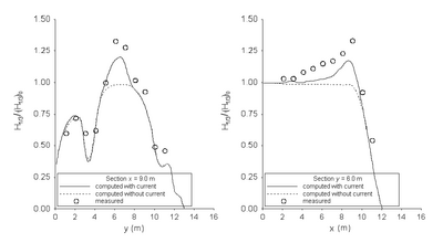
Figure 71. Normalized wave height comparisons of unidirectional incident waves along longitudinal (left) and transverse (right) transects with the Battjes and Janssen formula.
Chawla and Kirby formula
Figures 72 to 75 present the wave height contours for directional and unidirectional incident waves with and without a current using the depth-limiting breaking formula by Chawla and Kirby (2002). The model performs better with the current included. Changing the breaker coefficient from 0.6 to 1.0 increases the nearshore wave height.
Figure 76 compares calculated wave heights with the measurements. The simulation based on the Chawla and Kirby formula with the breaker coefficient equal to 1.0 tends to overestimate the wave height if the measured normalized height is less than 0.75. Figures 77 and 78 compare measured and calculated wave heights along the longitudinal and transverse transects for directional and unidirectional waves, respectively. CMS-Wave predicts the wave height well with a current present. Similar to the results from the Extended Miche formula and the Extended Goda formula, the calculated wave heights are greater than the measurements in front of the headland.
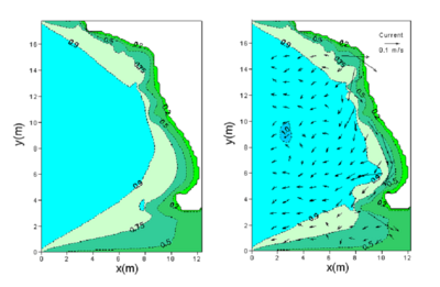
Figure 72. Calculated wave height contours for directional incident waves without current (left) and with current (right) by the Chawla and Kirby formula with of 0.6.
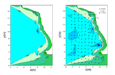
Figure 73. Calculated wave height contours for directional incident waves without current (left) and with current (right) by the Chawla and Kirby formula with of 1.0.
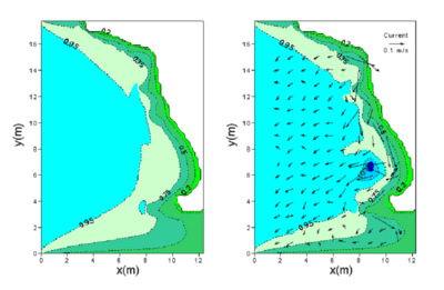
Figure 74. Calculated wave height contours for unidirectional incident waves without current (left) and with current (right) by the Chawla and Kirby formula with of 0.6.
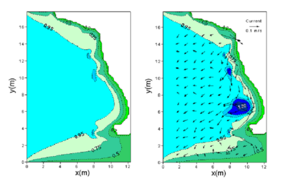
Figure 75. Calculated wave height contours for unidirectional incident waves without current (left) and with current (right) by the Chawla and Kirby formula with of 1.0.
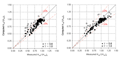
Figure 76. Measured versus calculated wave heights for directional (left) and unidirectional (right) incident waves with the Chawla and Kirby formula.
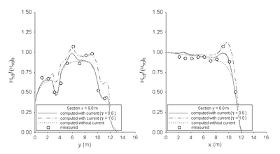
Figure 77. Normalized wave height comparisons of directional incident waves along longitudinal (left) and transverse (right) transects with the Chawla and Kirby formula.
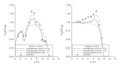
Figure 78. Normalized wave height comparisons of unidirectional incident waves along longitudinal (left) and transverse (right) transects with the Chawla and Kirby formula.
Two statistical parameters were considered for evaluating CMS-Wave performance with a current using different depth-limited wave breaking formulas. The first statistic is the mean relative error for the normalized significant wave height, defined as
\[{{\varepsilon }_{\text{err}}}=\frac{1}{M}\underset{l=1}{\overset{M}{\mathop \Sigma }}\,\left| \frac{{{\left[ \frac{{{H}_{1/3}}}{{{({{H}_{1/3}})}_{0}}} \right]}_{c}}-{{\left[ \frac{{{H}_{1/3}}}{{{({{H}_{1/3}})}_{0}}} \right]}_{m}}}{{{\left[ \frac{{{H}_{1/3}}}{{{({{H}_{1/3}})}_{0}}} \right]}_{m}}} \right|\times 100%\]
where l and M denote a sample wave height index and total numbers of wave height data, respectively; and the subscripts m, c, and 0 denote the measured, calculated, and incident wave height, respectively. The smaller the mean relative error, the better the prediction compares to the measurements. A value of zero implies a perfect match between measurements and calculations. The second statistical measure is the correlation coefficient between measured and calculated normalized wave heights.
Table 14 presents the two statistics calculated for the wave height estimates in simulations with a current present for the different breaking formulas. Mean relative errors for the normalized wave height estimates are usually small, less than 10 percent, and correlation coefficients are high, between 0.84 and 0.95, for all four wave breaking formulas examined. The Battjes and Janssen formula appears to provide the best wave height estimates among the four breaking formulas examined. The Chawla and Kirby (2002) formula, the Extended Goda (Sakai et al. 1989), and Extended Miche (Battjes 1972; Mase et al. 2005b) formula with a smaller breaker coefficient produce better estimates. Although the statistics point to a good performance index, it should be noted that the Chawla and Kirby (2002) formula with smaller breaker coefficient fails to predict the wave height near the shore. These numerical simulations demonstrate the importance of including the nearshore current in the wave transformation calculation regardless of which depth-limited breaking formula is applied, if a current is present.
Table 14. Statistical mean relative errors and correlation coefficients.
| Breaking Formula | Unidirectional Incident Waves | Directional Incident Waves | ||
| 'err '(%) | Correlation Coefficient | 'err '(%) | Correlation Coefficient | |
| Extended Miche (a = 0.14) | 6.26 | 0.91 | 8.75 | 0.87 |
| Extended Miche (a = 0.129) | 5.76 | 0.93 | 8.25 | 0.89 |
| Extended Goda (A = 0.17) | 6.15 | 0.92 | 8.93 | 0.87 |
| Extended Goda (A = 0.15) | 4.93 | 0.95 | 7.63 | 0.91 |
| Battjes and Janssen | 5.42 | 0.94 | 7.67 | 0.92 |
| Chawla and Kirby ( = 0.6) | 5.62 | 0.94 | 5.94 | 0.92 |
| Chawla and Kirby ( = 1.0) | 6.77 | 0.89 | 9.17 | 0.84 |
| Table of Contents | Chapter 5 - Field Applications |