CMS-Wave Model Parameters: Difference between revisions
mNo edit summary |
|||
| (7 intermediate revisions by one other user not shown) | |||
| Line 1: | Line 1: | ||
[[File:CMSWave Model Parameters GeneralTab V13.2.12.png|thumb|right|400px|CMS-Wave Model Control window Version 13.2.12.]] | [[File:CMSWave Model Parameters GeneralTab V13.2.12.png|thumb|right|400px|CMS-Wave Model Control window Version 13.2.12.]] | ||
= Parameters = | = Parameters = | ||
[[File:CMS Wave Model Control V. 13.2.12.png|500px|thumb|center]] | |||
==CMS Wave plane mode == | ==CMS Wave plane mode == | ||
| Line 20: | Line 21: | ||
==Surge Fields== | ==Surge Fields== | ||
==Wind Fields== | ==Wind Fields== | ||
If the spatial wind field input is required, users shall prepare a wind.dat file or *.wind (in the same format as *.cur) to provide the x- and y-component wind data corresponding to the incident wave conditions in the model grid. | |||
==Matrix Solver== | ==Matrix Solver== | ||
https://cirpwiki.info/wiki/CMSFlow_Matrix_Solver | https://cirpwiki.info/wiki/CMSFlow_Matrix_Solver | ||
= Boundary control = | = Boundary control = | ||
[[File:CMS Wave Model Control Boundray ControlV. 13.2.12.png|500px|thumb|center]] | |||
Water level and wind information are optional source as specified under | Water level and wind information are optional source as specified under | ||
Wave Source in addition to the spectral input data. | Wave Source in addition to the spectral input data. | ||
==Source== | ==Source== | ||
Spatially varied spectral input – This is simply the case as in a child grid that spatially varied wave spectra are permitted to assign at user specified locations along or near the seaward boundary of the child grid. To apply spatially varied spectra for wave input without a parent grid, users will need to prepare the wave input file with the format as described in the child grid run. | |||
https://cirpwiki.info/wiki/CMS-Wave_Input_Spectra | https://cirpwiki.info/wiki/CMS-Wave_Input_Spectra | ||
| Line 67: | Line 71: | ||
= Output control = | = Output control = | ||
[[File:CMS Wave Model Control OutputControl. 13.2.12.png|500px|thumb|center]] | |||
== Limit observation output == | == Limit observation output == | ||
== Radiation stresses == | == Radiation stresses == | ||
| Line 73: | Line 78: | ||
= Options = | = Options = | ||
[[File:CMS Wave Model Control Options 13.2.12.png|500px|thumb|center]] | |||
To include (trigger) either of wave run-up, infra-gravity wave, nonlinear wave-wave interaction, binary (xmdf or *.h5) output, multiple processors, muddy bed, and spatial wind field input is just a one-click step in the SMS interface. Additional files are required for the muddy bed and spatial wind field input. | To include (trigger) either of wave run-up, infra-gravity wave, nonlinear wave-wave interaction, binary (xmdf or *.h5) output, multiple processors, muddy bed, and spatial wind field input is just a one-click step in the SMS interface. Additional files are required for the muddy bed and spatial wind field input. | ||
==[https://cirpwiki.info/wiki/CMS-Flow_NUmerical_Methods:_Wetting_and_Drying Allow wetting and drying]== | ==[https://cirpwiki.info/wiki/CMS-Flow_NUmerical_Methods:_Wetting_and_Drying Allow wetting and drying]== | ||
| Line 83: | Line 89: | ||
==Fast-mode run== | ==Fast-mode run== | ||
==Roller effects== | ==Roller effects== | ||
The wave roller parametric formulation is commonly applied in the wave spectral model to modify breaking wave energy dissipation nearshore to mimic better the surf zone dynamics. The wave roller effect used in CMS-Wave is based on the roller model developed by Zhang et al. (2014). | |||
==Forward reflection== | ==Forward reflection== | ||
==Backward reflection== | ==Backward reflection== | ||
| Line 113: | Line 121: | ||
|3. [[Wave_CardFormat2|Card-based - [card name] [value(s)]]] || '''(Used with SMS 13.2 and after)''' | |3. [[Wave_CardFormat2|Card-based - [card name] [value(s)]]] || '''(Used with SMS 13.2 and after)''' | ||
|} | |} | ||
Later versions of SMS can generally read the older formats, however exceptions have been found with Type 1 and listed on that page. | |||
[[CMS-Wave_File_Formats | Back to CMS-Wave File Formats]] | [[CMS-Wave_File_Formats | Back to CMS-Wave File Formats]] | ||
Latest revision as of 21:24, 9 April 2025
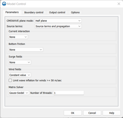
Parameters
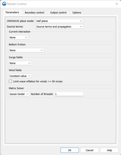
CMS Wave plane mode
Full half plane with reverse spectra
Full plane
In this mode, CMS-Wave performs two half-plane runs in the same grid. The first run is in the half-plane with the principle wave direction toward the shore. The second run is in the seaward half-plane as opposed to the first run. Upon the completion of the second run, two half-plane results are combined to one full-plane solution (Lin et al. 2012). Because the run time for the full-plane is approximately twice of the regular half-plane, users shall consider the full-plane mode only if the full-plane features like wave generation and propagation in a bay or around an island.
Half Plane
Source terms
CMS-Wave is a phase-averaged model for propagation of directional irre-gular waves over complicated bathymetry and nearshore where wave re-fraction, diffraction, reflection, shoaling, and breaking simultaneously act at inlets. Wave diffraction terms are included in the governing equations following the method of Mase et al. (2005). Four different depth-limiting wave breaking formulas can be selected as options including the interaction with a current. The wave-current interaction is calculated based on the dispersion relationship including wave blocking by an opposing current (Larson and Kraus 2002). Wave generation and whitecapping dissipation are based on the parameterization source term and calibration using field data (Lin and Lin 2004a and b, 2006a). Bottom friction loss is estimated from the classical drag law formula (Collins 1972).
Current interaction
Bottom friction
Bottom friction could be assigned as constant or by a dataset inside SMS. To see more details, see the Bottom and wall friction of the CMS Flow. Usually, the same roughness method used on CMS Wave is used on the CMS Flow parameters bottom friction. For a detail explanation of how Bottom Friction variable is used on the CMS Wave model, see Bottom Friction
Surge Fields
Wind Fields
If the spatial wind field input is required, users shall prepare a wind.dat file or *.wind (in the same format as *.cur) to provide the x- and y-component wind data corresponding to the incident wave conditions in the model grid.
Matrix Solver
https://cirpwiki.info/wiki/CMSFlow_Matrix_Solver
Boundary control
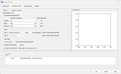
Water level and wind information are optional source as specified under Wave Source in addition to the spectral input data.
Source
Spatially varied spectral input – This is simply the case as in a child grid that spatially varied wave spectra are permitted to assign at user specified locations along or near the seaward boundary of the child grid. To apply spatially varied spectra for wave input without a parent grid, users will need to prepare the wave input file with the format as described in the child grid run.
https://cirpwiki.info/wiki/CMS-Wave_Input_Spectra
Interpolation
- Inverse distance weighting
The inverse-distance interpolation also referred to as Shepard interpola-tion is given by (Shepard 1968)
| (17-1) |
where the interpolation weights are given by
| (17-2) |
where
= real and positive power parameter [-]
d = distance between the known points and the unknown interpolation points equal to the Euclidean norm .
In this interpolation, the weight of each point decreases with distance from the interpolated point. One advantage of the inverse-distance interpolation is the interpolation weights are independent of the interpolation function, and therefore only need to be calculated once and can be saved for computational efficiency.[1]
Computational spectral grid
Spectral waves or wave parameters can be generated for the wave grid forcing, or wind direction and speeds can provide the necessary information for wind- wave generation. Full (directional) spectra can be imported into the SMS for the CMS-Wave, as well as simplified wave parameters (angle, wave height, and period, etc).
Sides
Case data
Wind direction angle conversion
- Cartesian
- Meteorologic
- Oceanographic
- Shore normal
Populate from Spectra
Set Reference Time
Output control
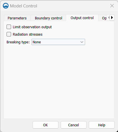
Limit observation output
Radiation stresses
Sea/swell
Breaking type
Options
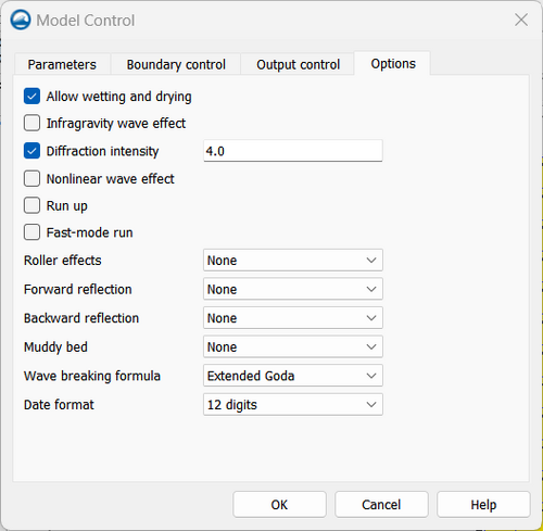
To include (trigger) either of wave run-up, infra-gravity wave, nonlinear wave-wave interaction, binary (xmdf or *.h5) output, multiple processors, muddy bed, and spatial wind field input is just a one-click step in the SMS interface. Additional files are required for the muddy bed and spatial wind field input.
Allow wetting and drying
Infragravity wave effect
Diffraction intensity
Nonlinear wave effect
Run up
Fast-mode run
Roller effects
The wave roller parametric formulation is commonly applied in the wave spectral model to modify breaking wave energy dissipation nearshore to mimic better the surf zone dynamics. The wave roller effect used in CMS-Wave is based on the roller model developed by Zhang et al. (2014).
Forward reflection
Backward reflection
Muddy bed
If the muddy bed calculation is required, users shall prepare a mud.dat file or *.mud (in the same format as *.dep) to list the spatial varying max-imum kinematic viscosity for the entire grid (recommended maximum kinematic viscosity for mud is 0.04 m2/sec).
Wave breaking formula
Date format
To setup the model parameters for CMS-Wave:
1. Go to CMS-Wave, Model Control, Options and turn on Allow wetting and drying and Bed friction
2. Users can also specify constant or varied forward and backward reflection coefficients in Settings,
To read more about CMS Wave defintions, see CMS Wave Model Control Definitions
CMS-Wave Model Control File formats
The CMS-Wave Options File (*.std) can have one of 3 input formats. Click one of the options below for the format description.
| 1. No cards - order of values on one line is very important. | (Used with SMS 11.1 and previous) |
| 2. Card-based - [value] [!card name] | (Used with SMS 11.2 to 13.1) |
| 3. Card-based - [card name] [value(s)] | (Used with SMS 13.2 and after) |
Later versions of SMS can generally read the older formats, however exceptions have been found with Type 1 and listed on that page.